How To Build
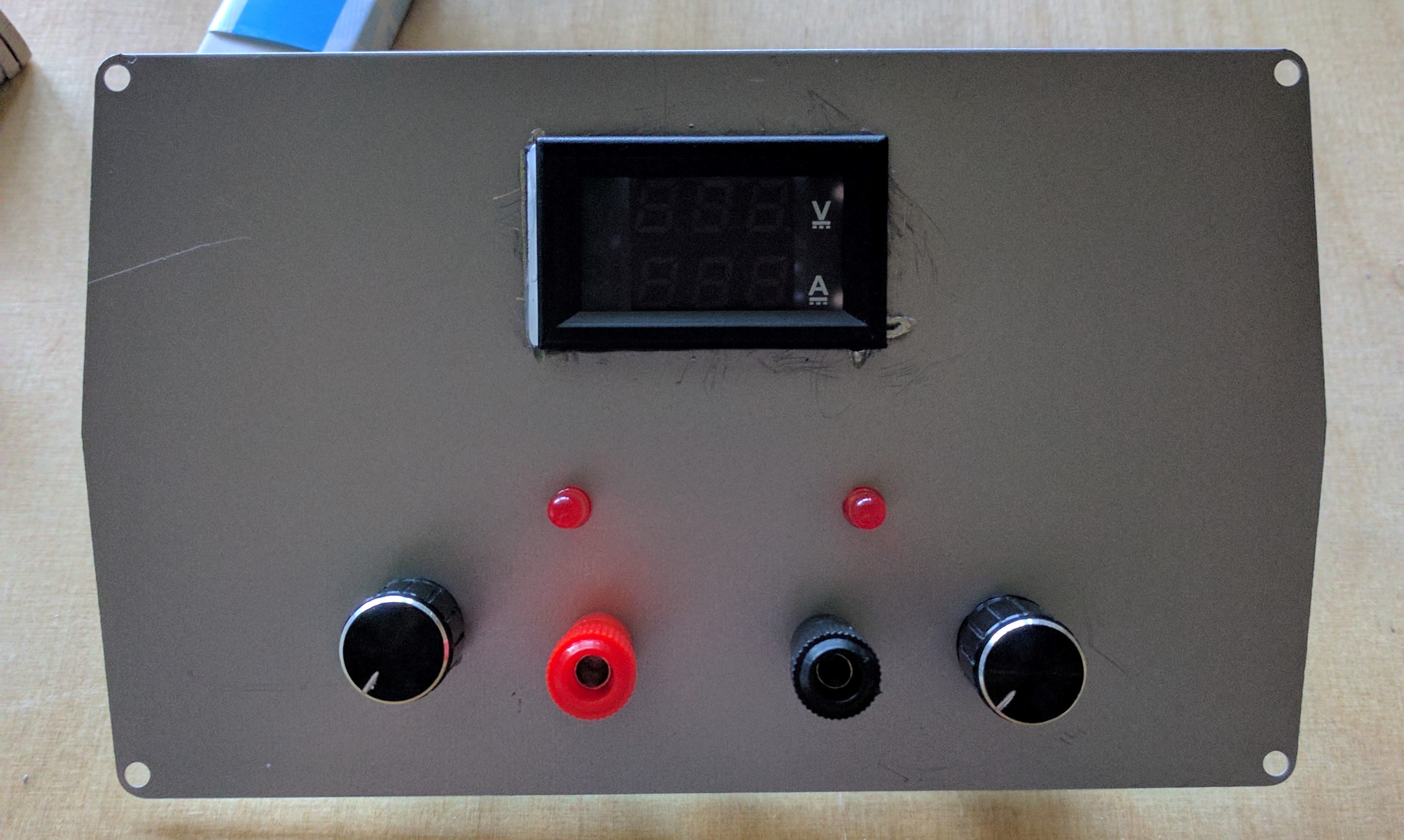
Front Panel
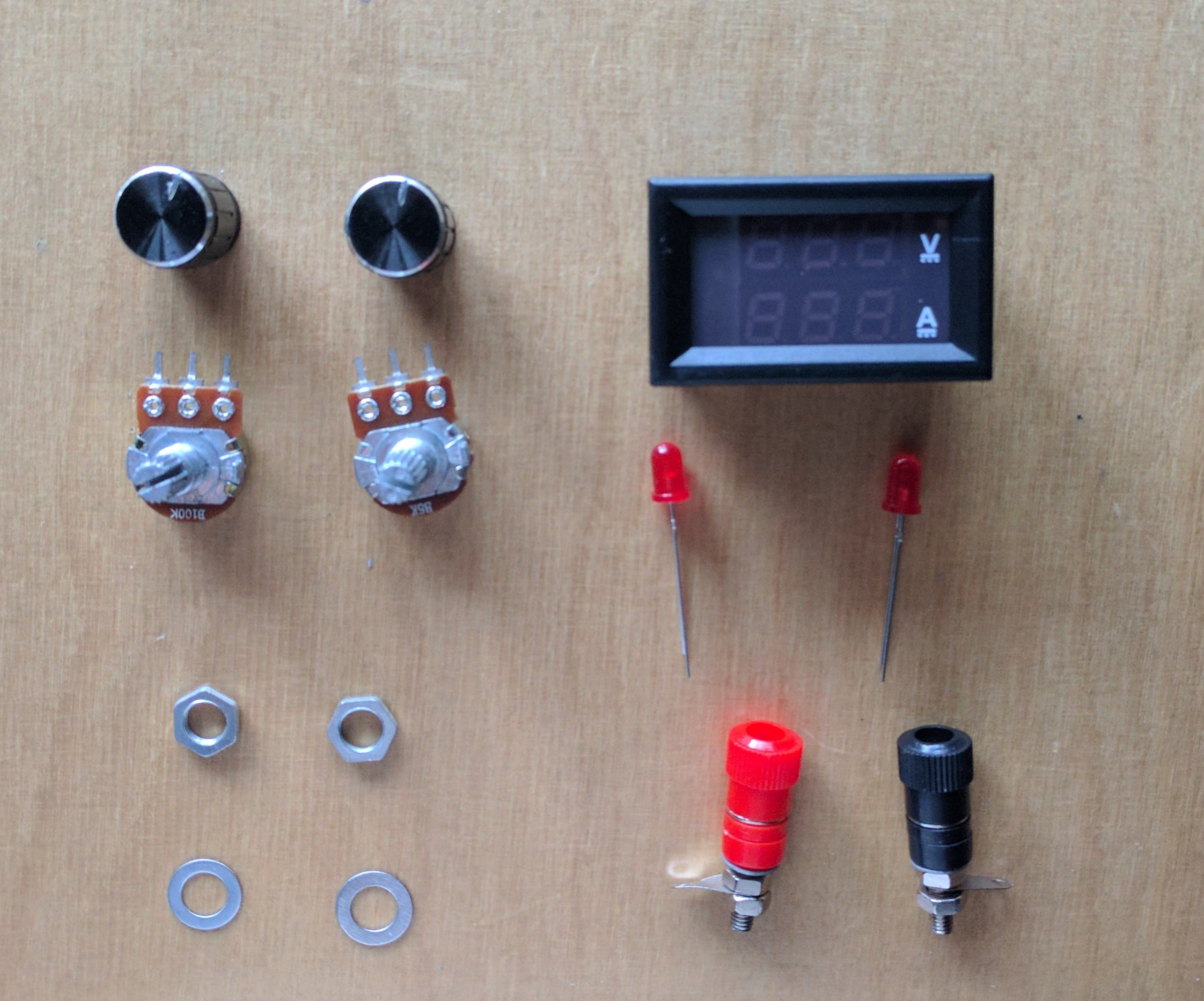
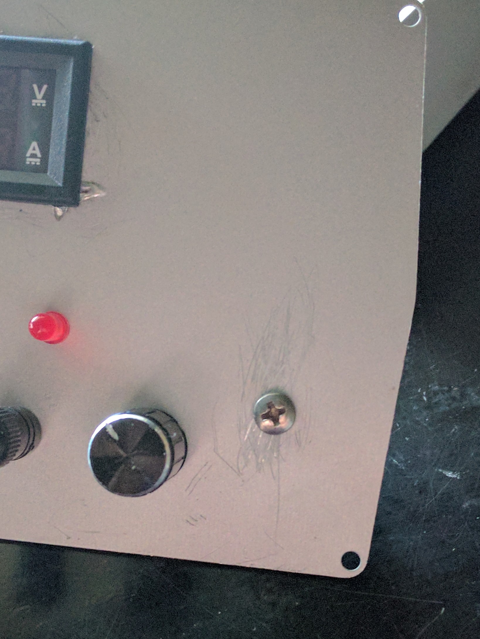
First, we take all the components that need to be placed on the front panel : Display, Potentiometers (P1 & P2), LEDs (D2 & D4) and finally the Bana Plug Jacks.
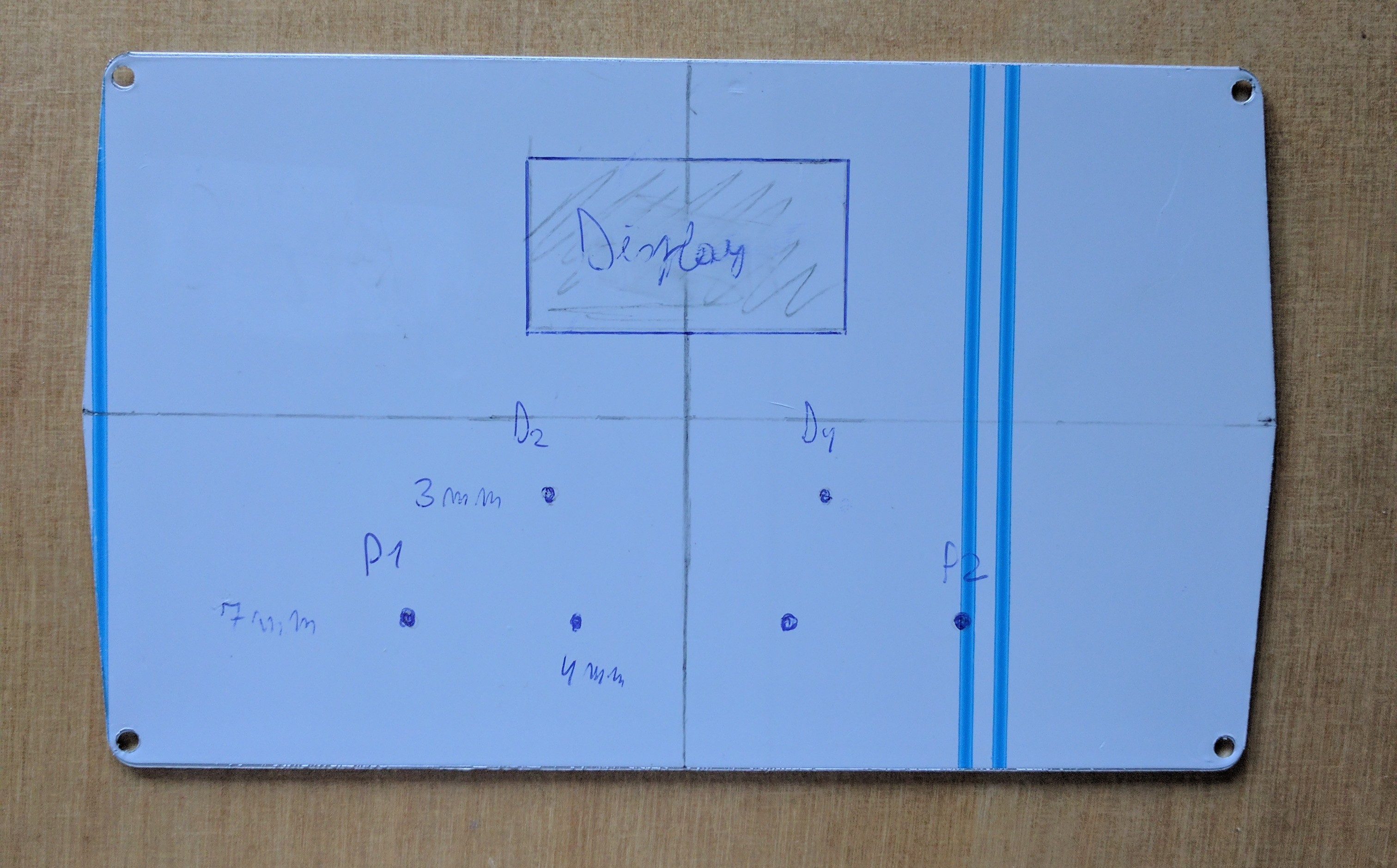
Then we outline the placement of these components on the front-panel.
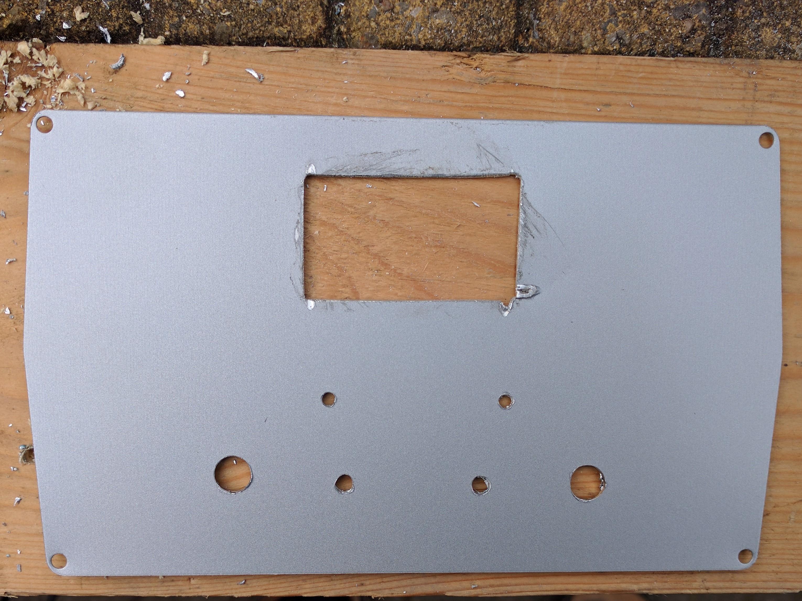
The next step is to cut these in such a way that the components can be placed.
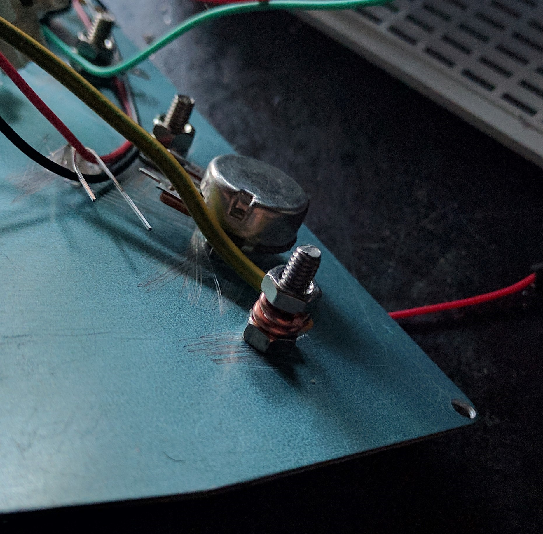
Finally, we mount the components on the panel with some hot glue and a pair of nuts and bolts.

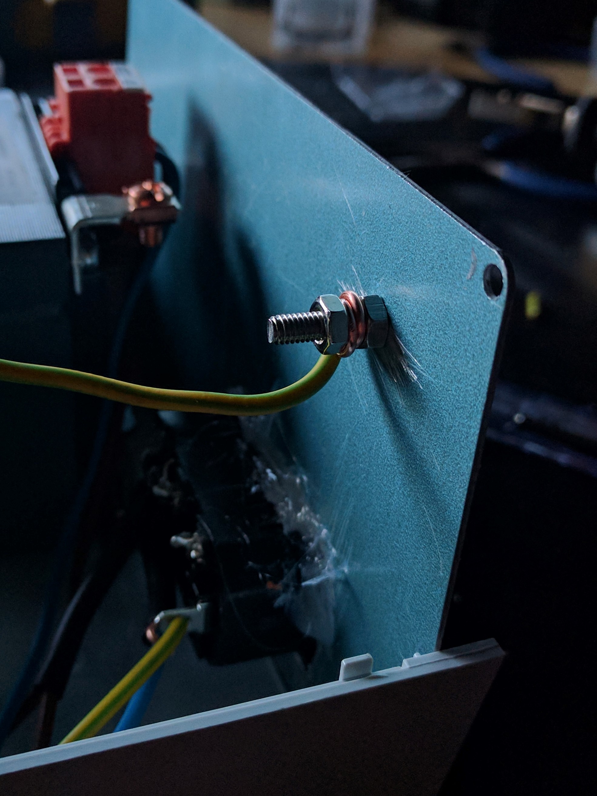
Do not forget to connect the front panel to ground.
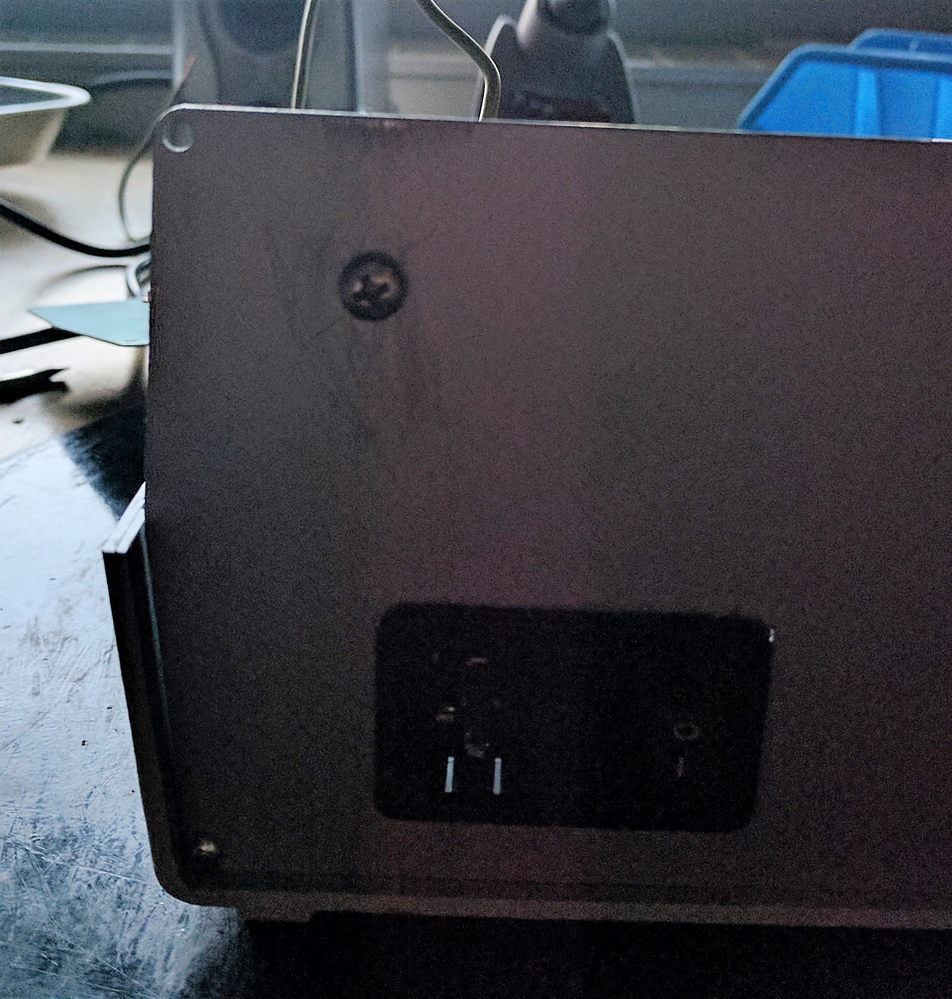
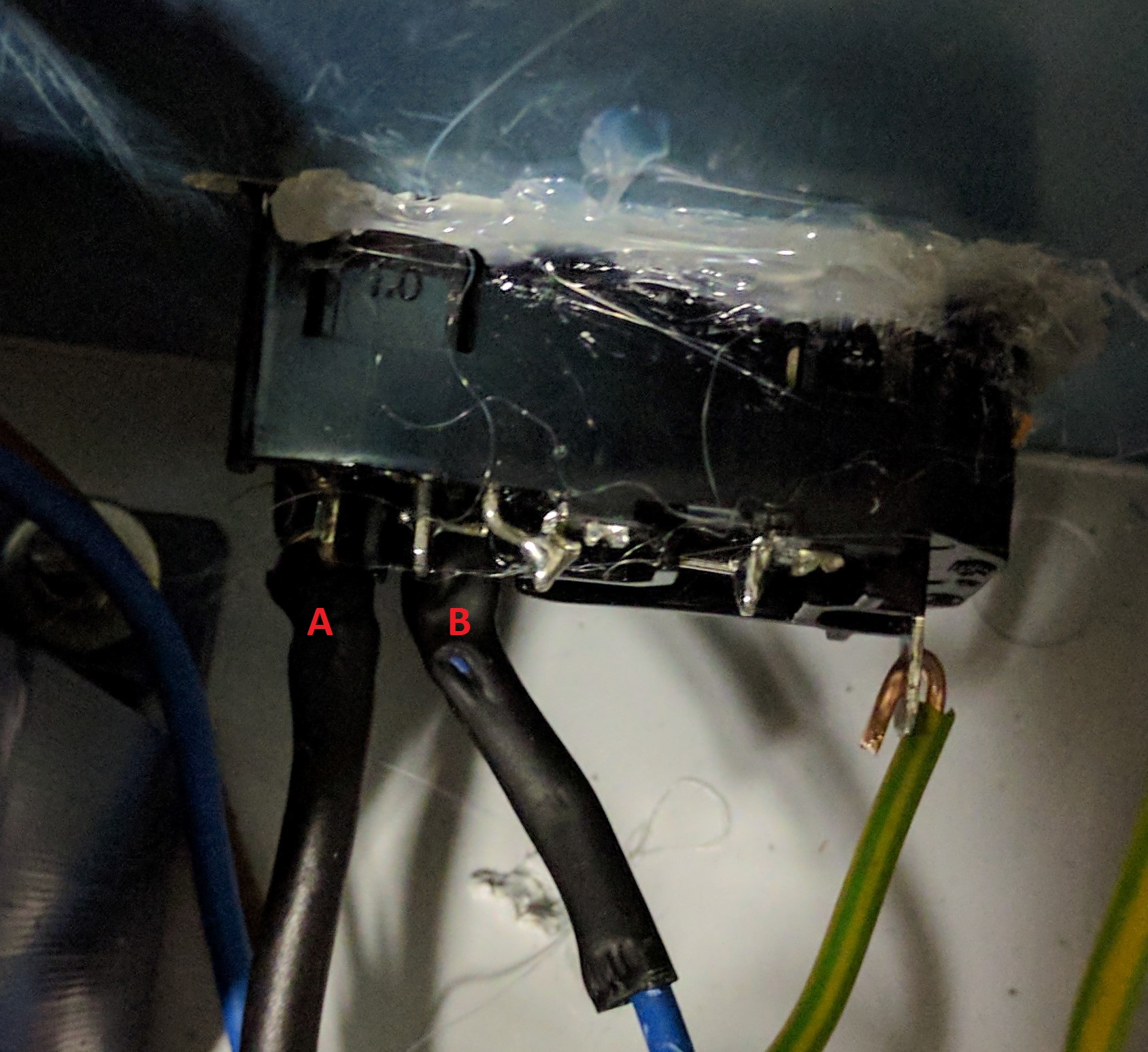
Back Panel
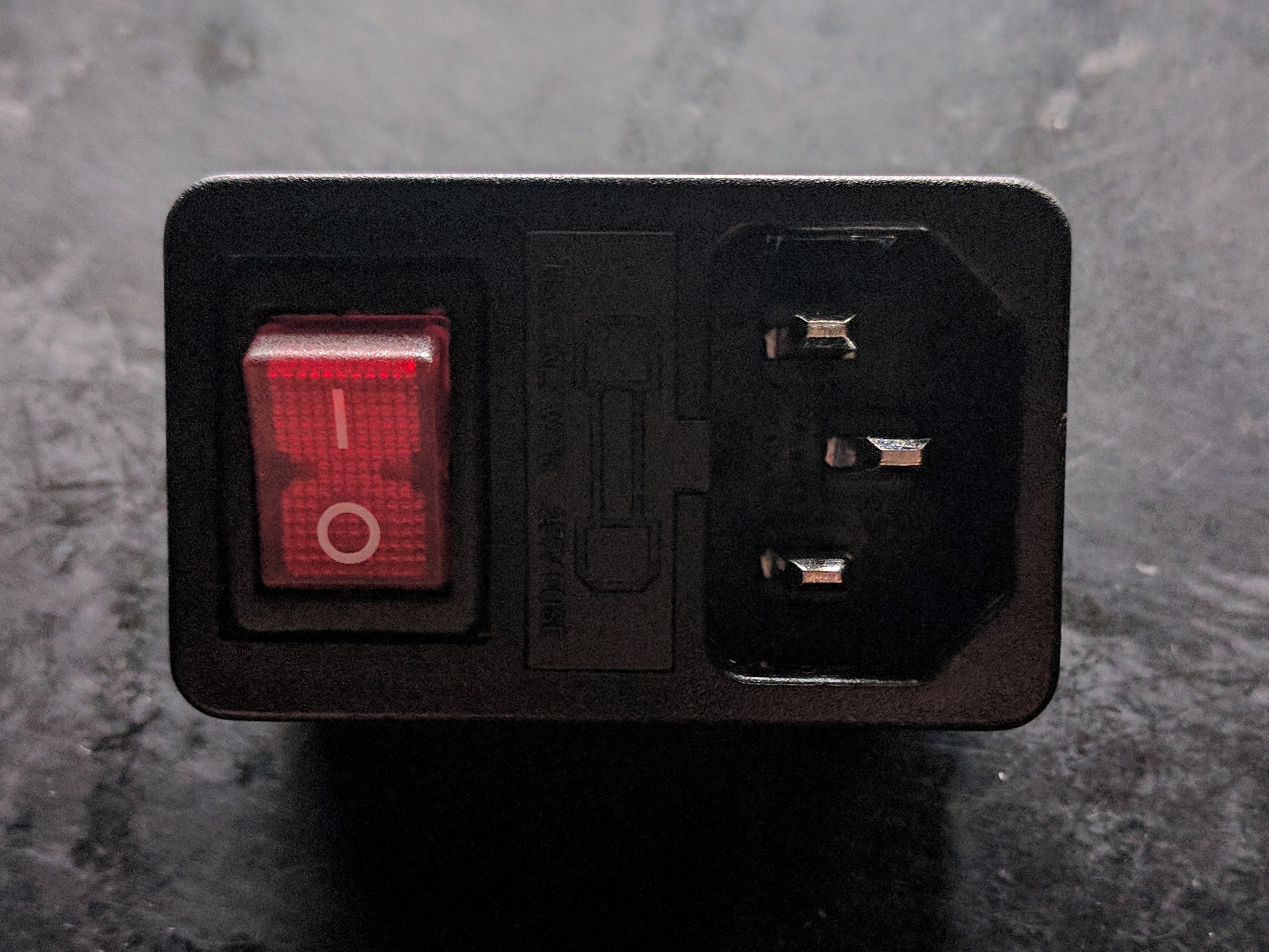
We start off by taking the switch and the fuse, and we put the fuse into the switch like shown below.
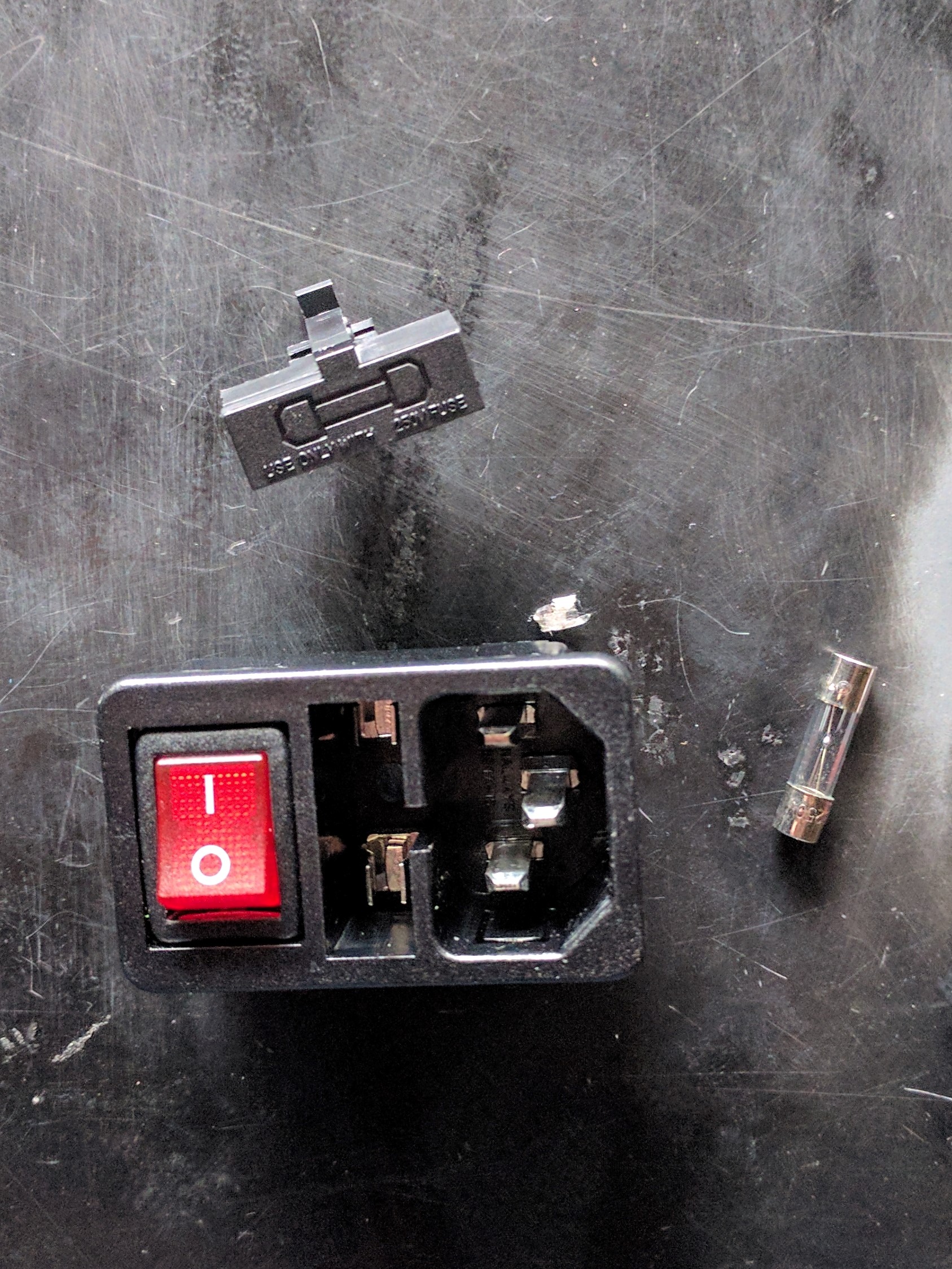
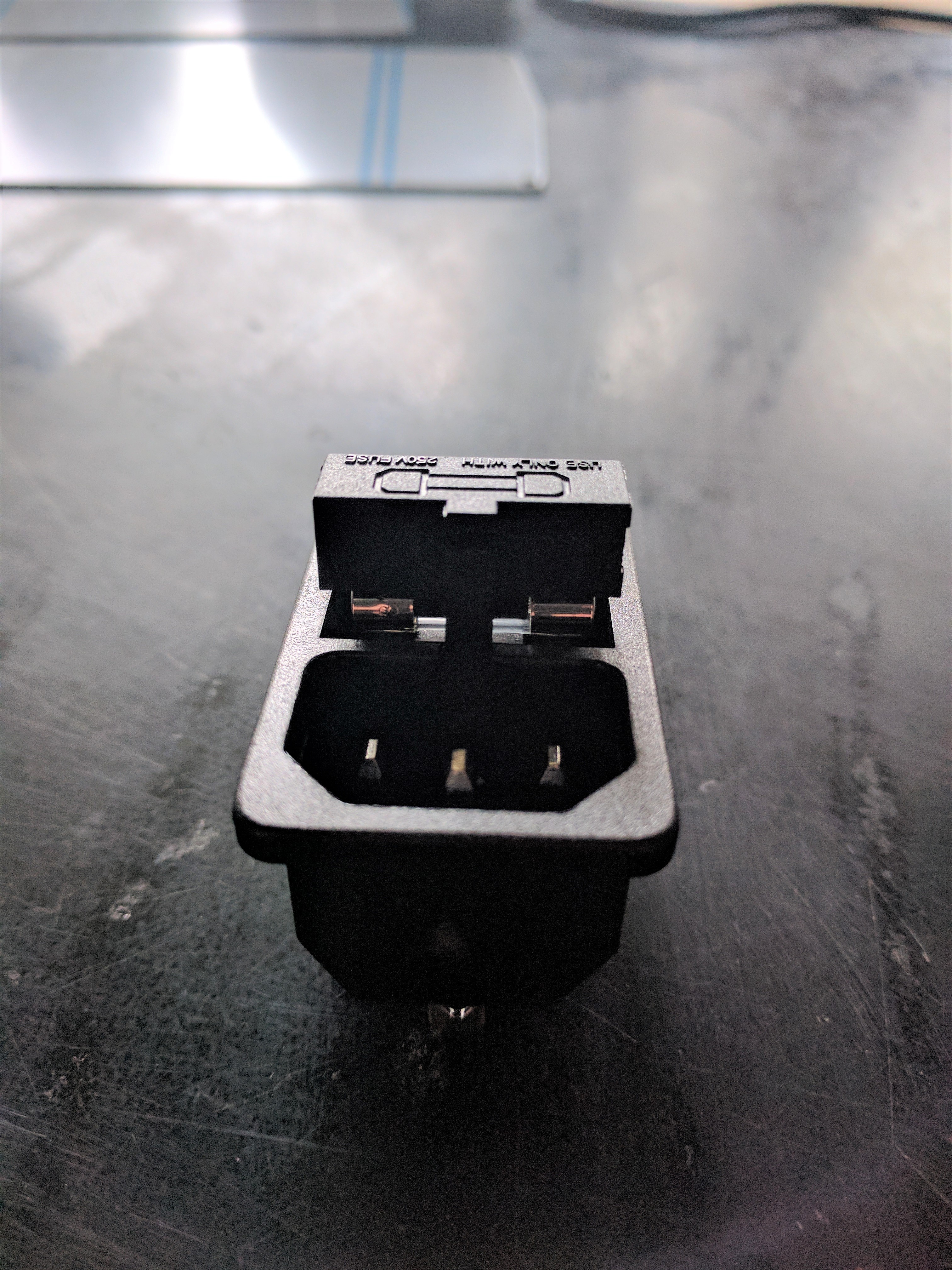
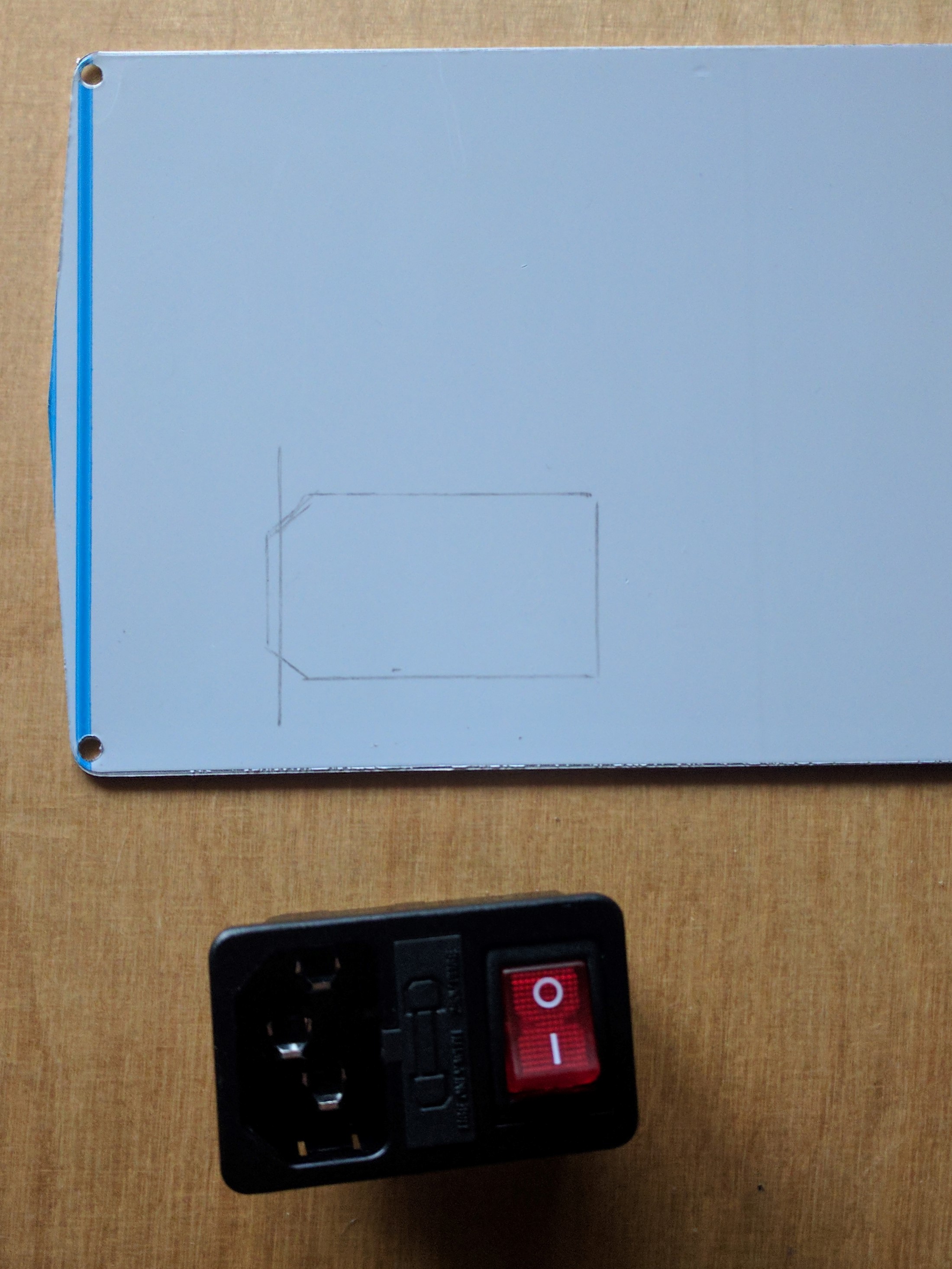
When the fuse is placed within the switch, we can make the necessary marks on the panel for assembly.
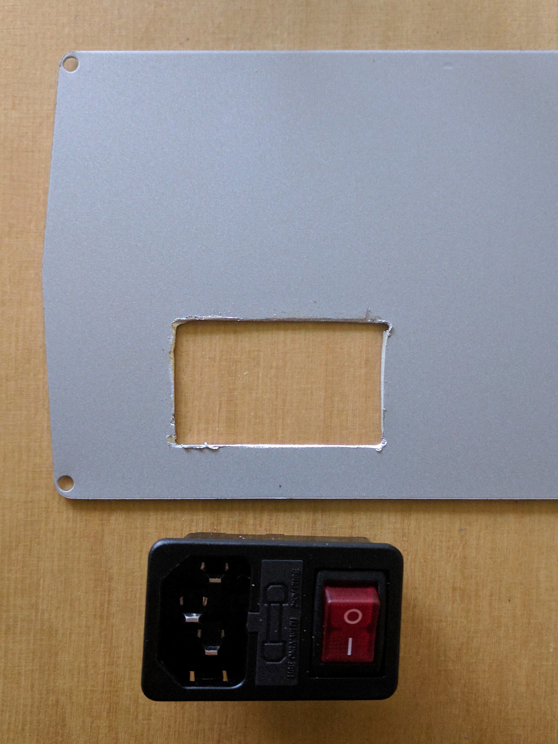
After the marks have been successfully drawn, these can be cut in such a way that the placement of the switch is made possible.
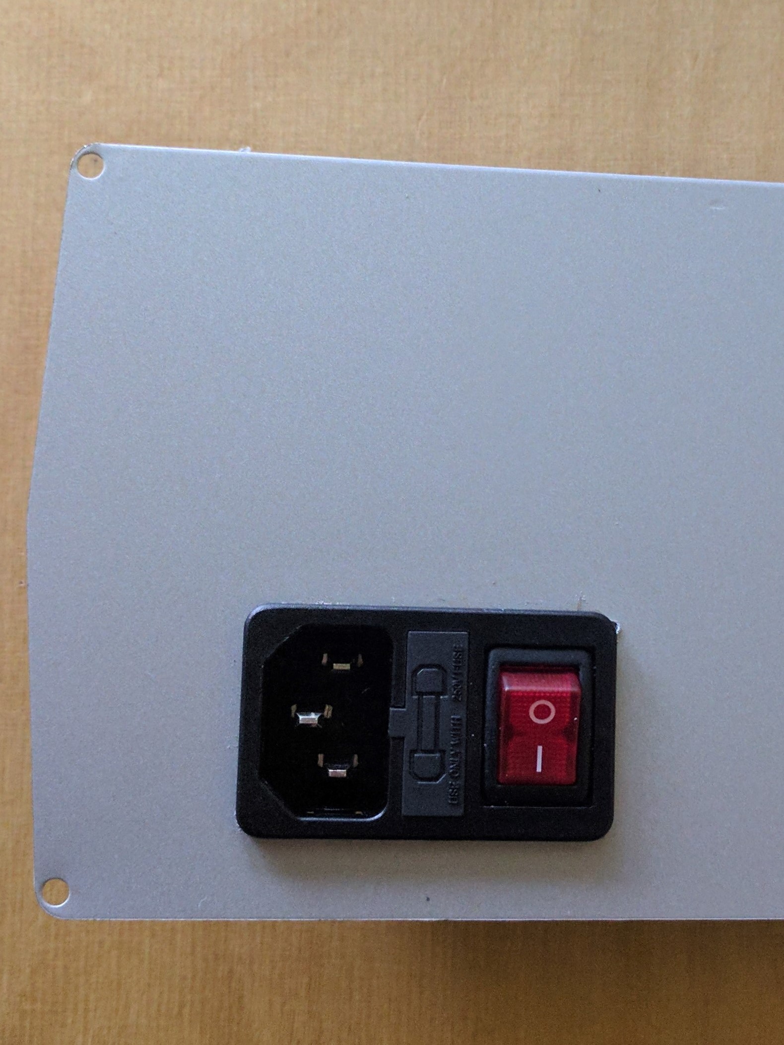
If the cut-out is done correctly, the switch should easily snap into its place.
Do not forget to connect the back panel to ground.
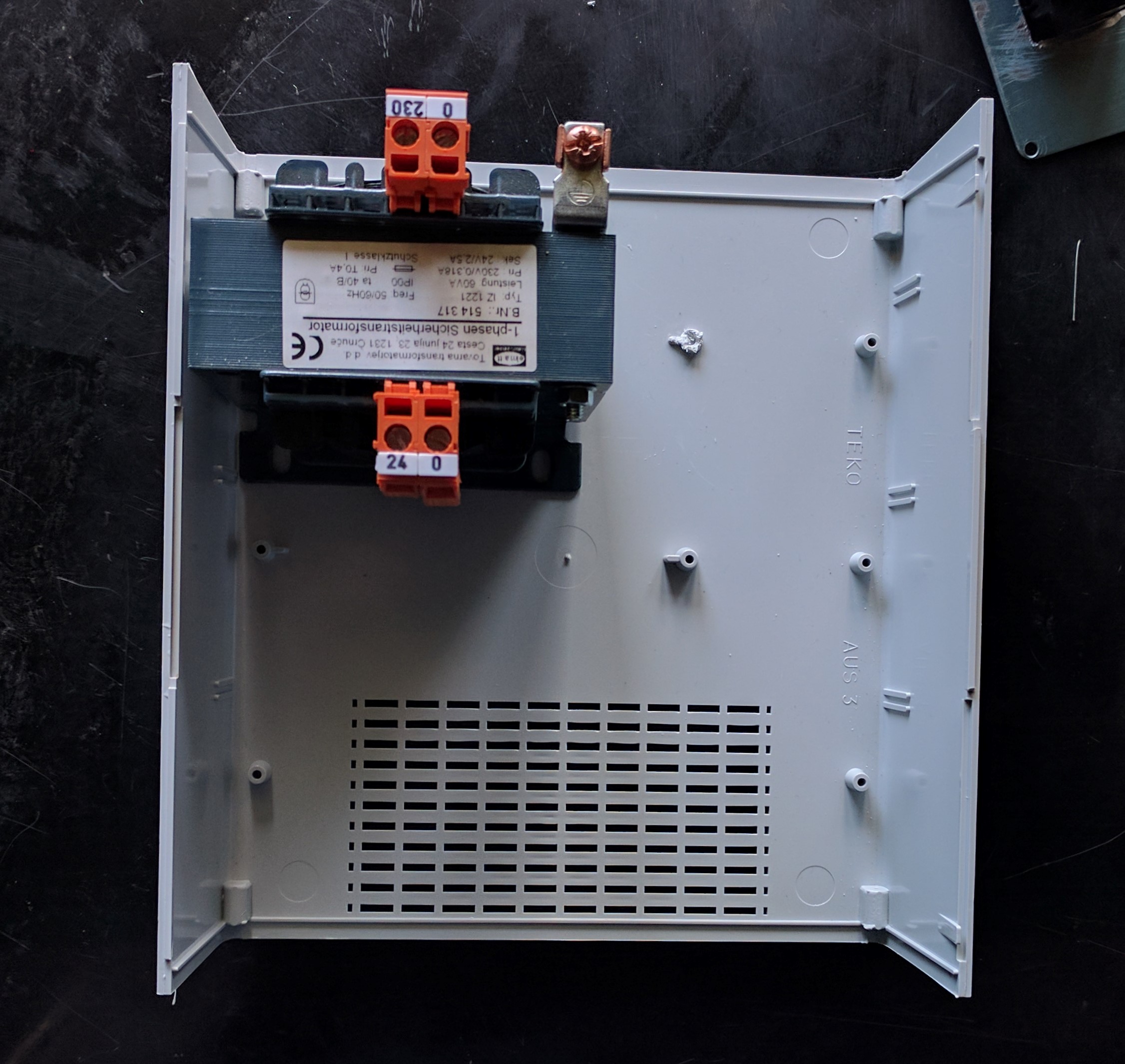
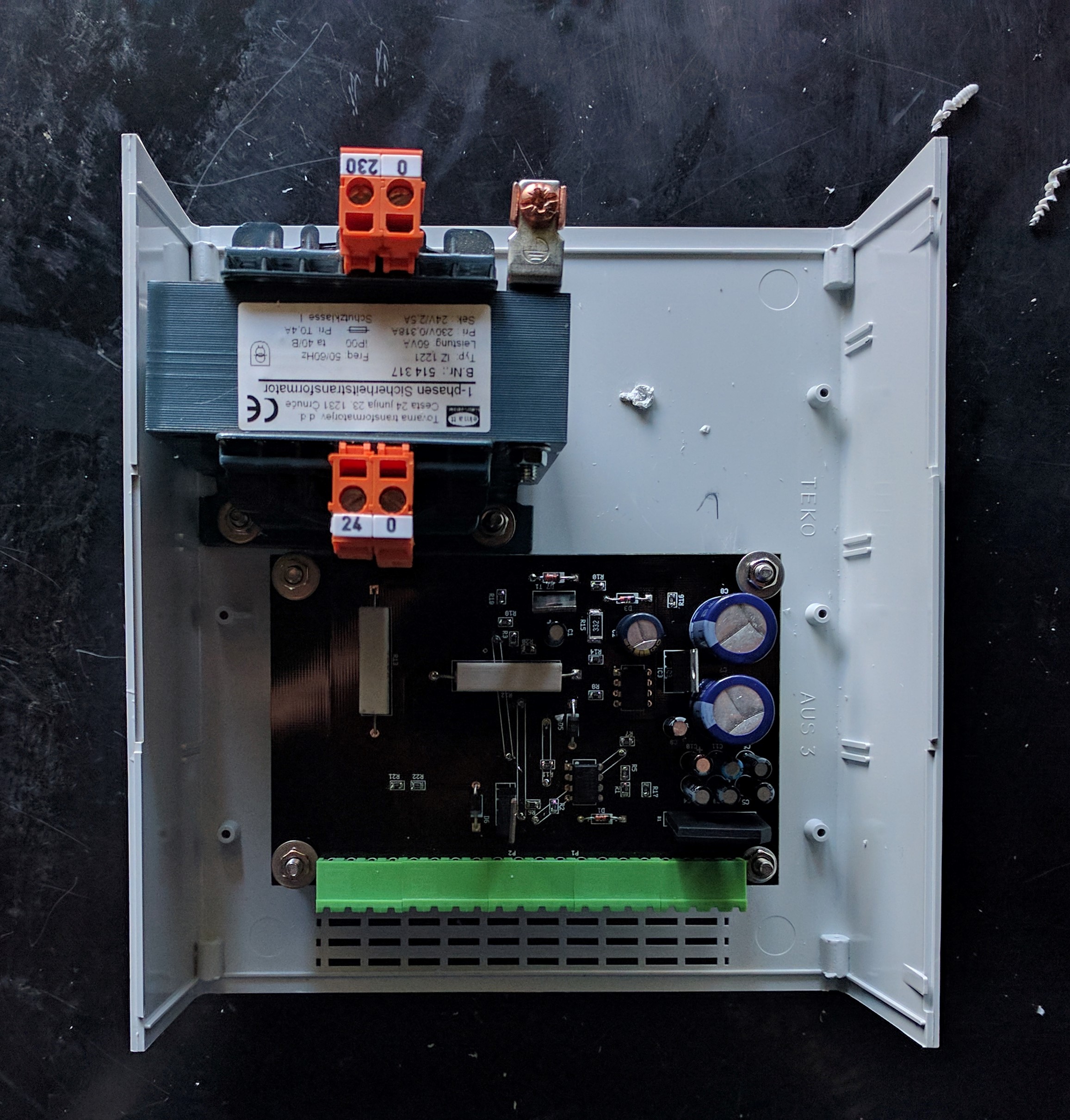
Transformer
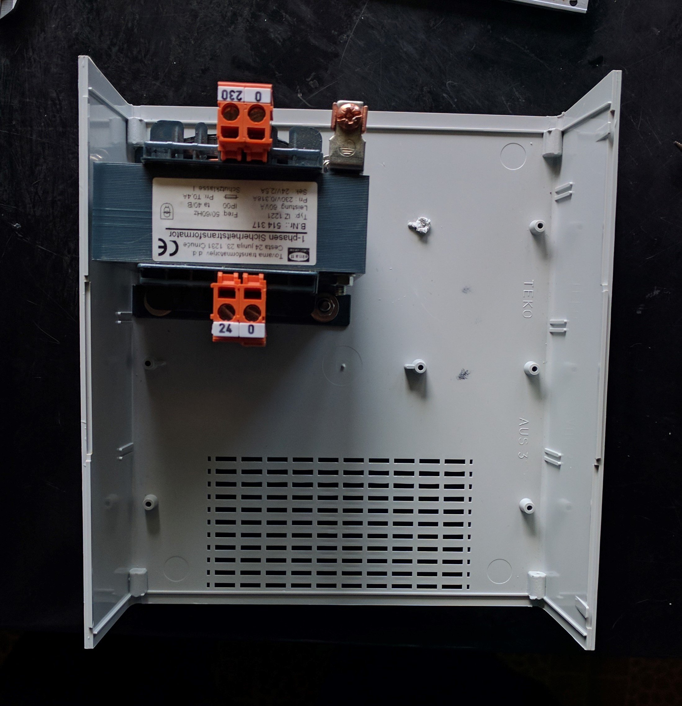
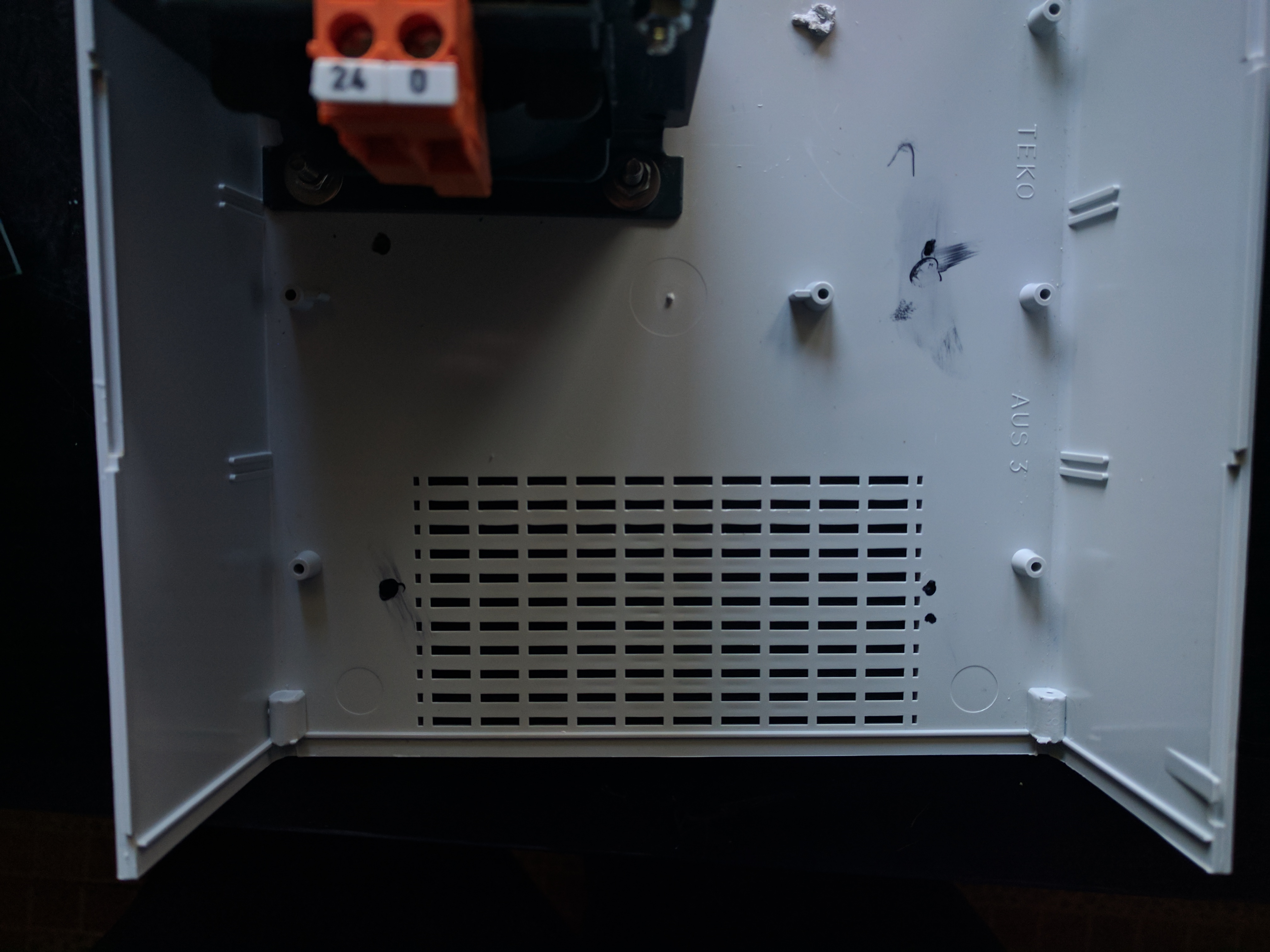
We place the 230V to 24V transformer in the case like so, and make the necessary marks for drilling.
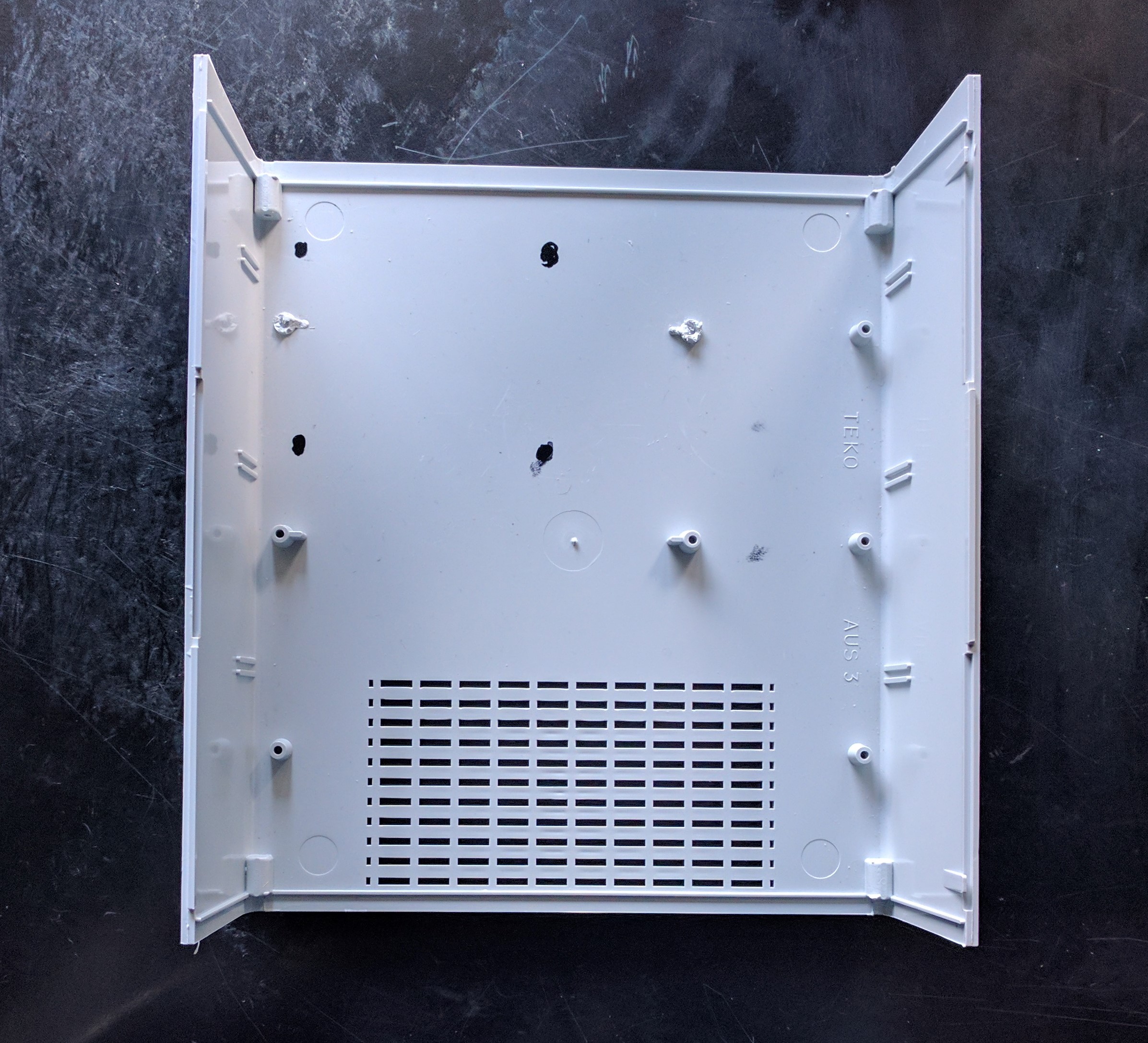
Then we drill the holes with a drill.
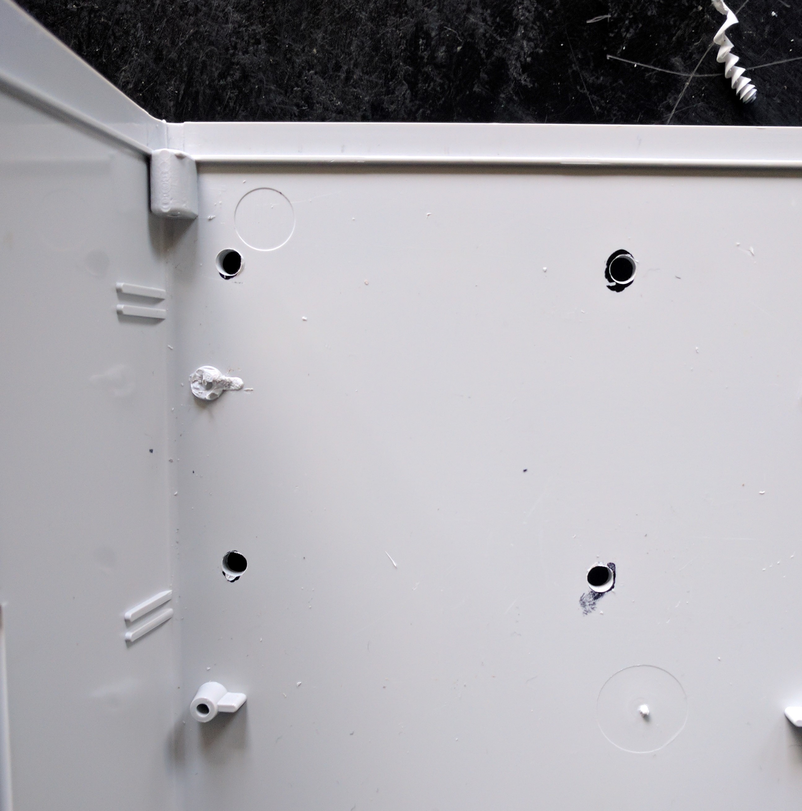
The final step is to mount the transformer using nuts and bolts.
PCB
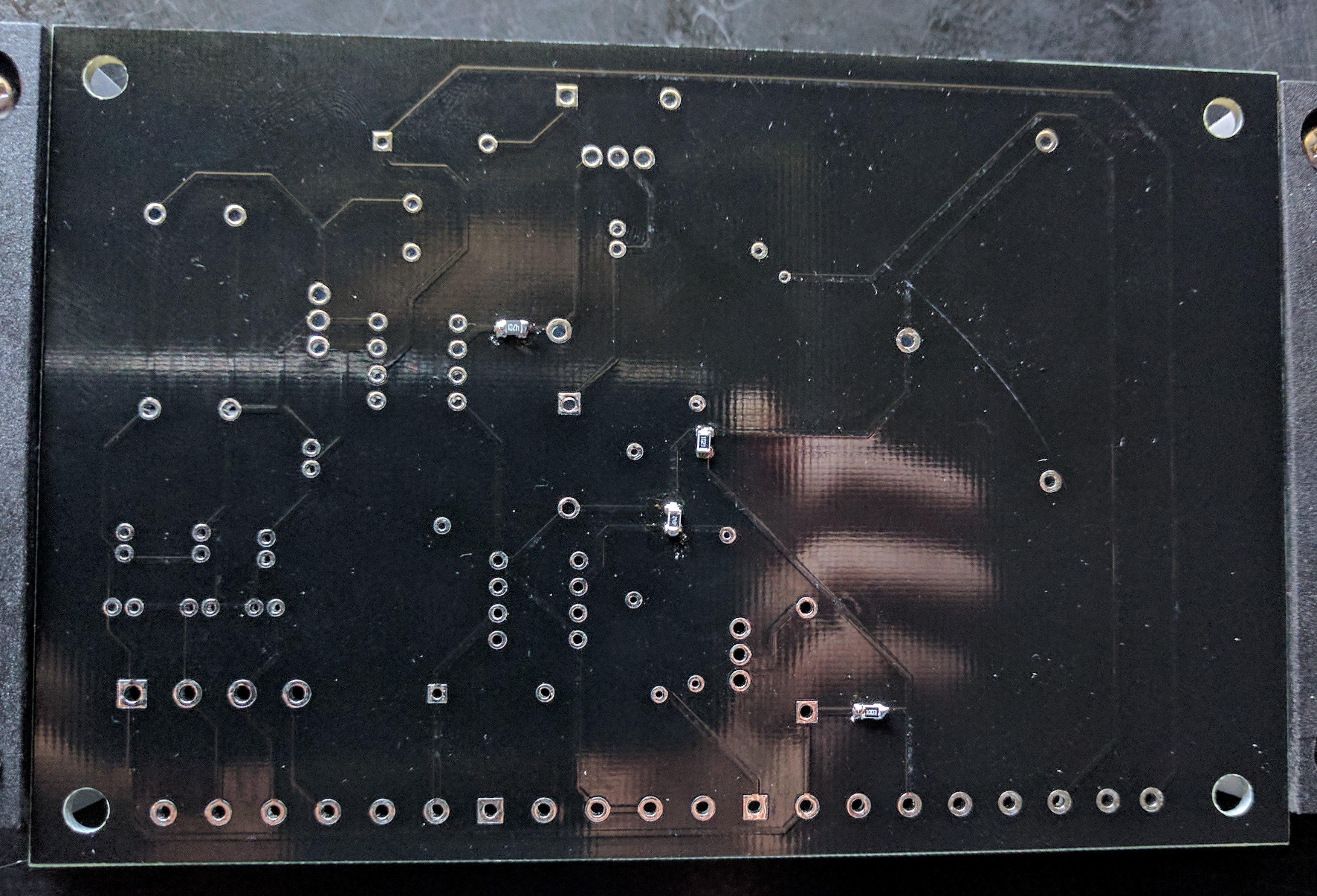
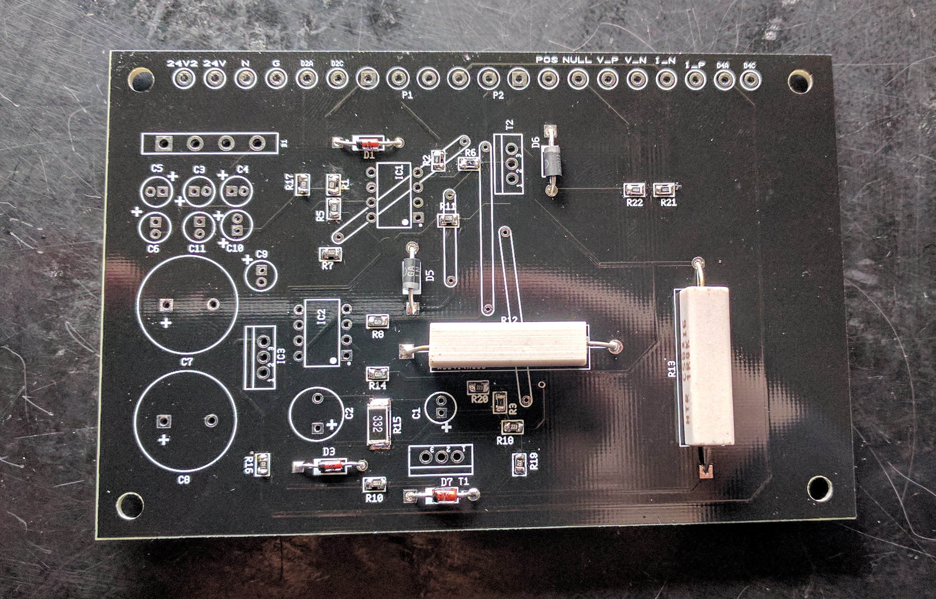
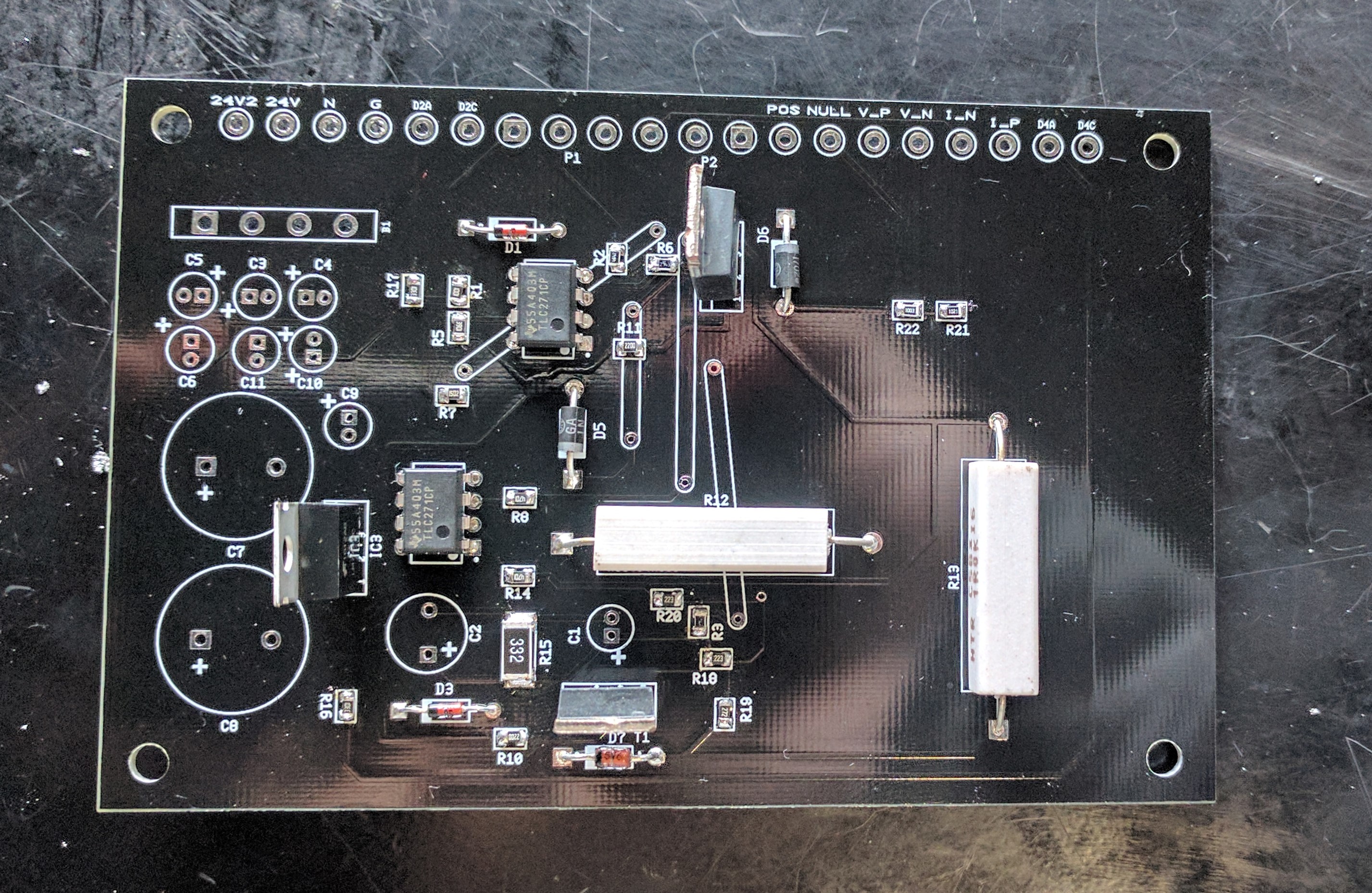
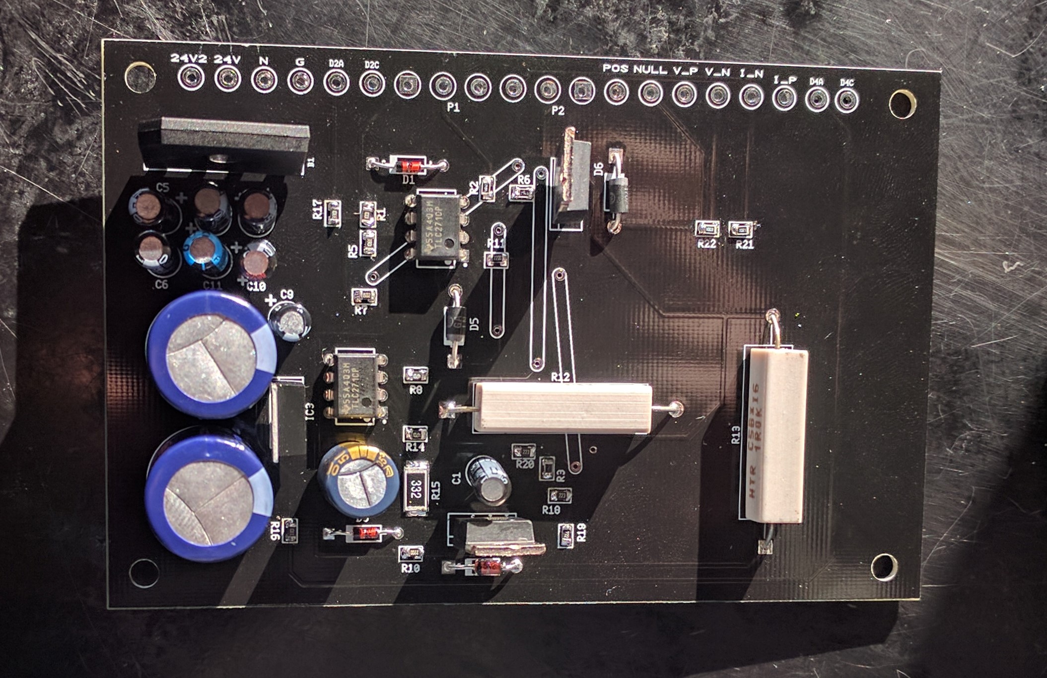
The first thing we do is take our beautiful PCB.
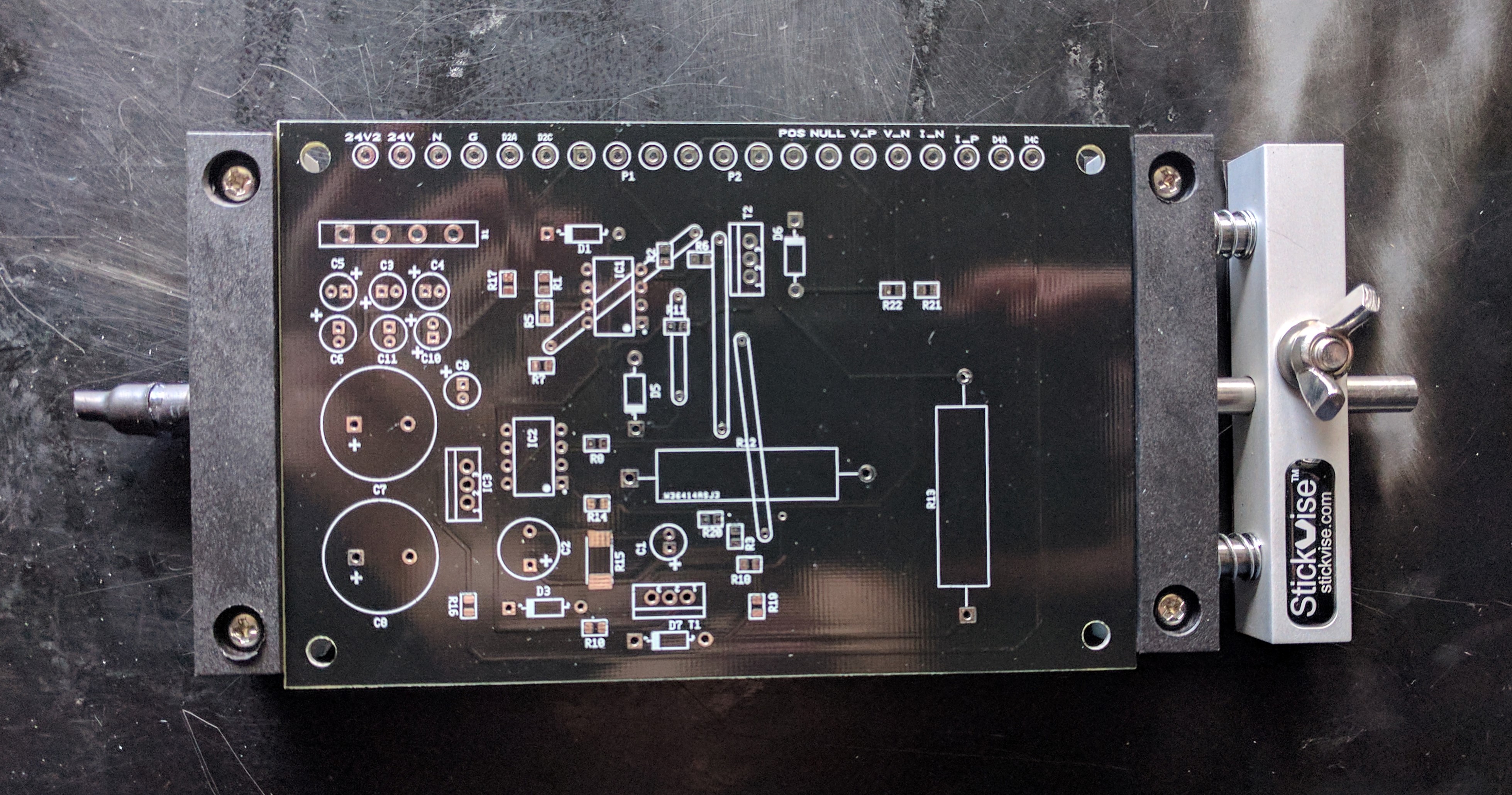
We decided to solder the resistors as a start.
In this case it is easier to solder the SMD resistors first.
Take the following components : R1, R2, R3, R4, R5, R6, R7, R8, R9, R10, R11, R14, R15, R16, R17, R18, R19, R20, R21, R22, R23 and R24.
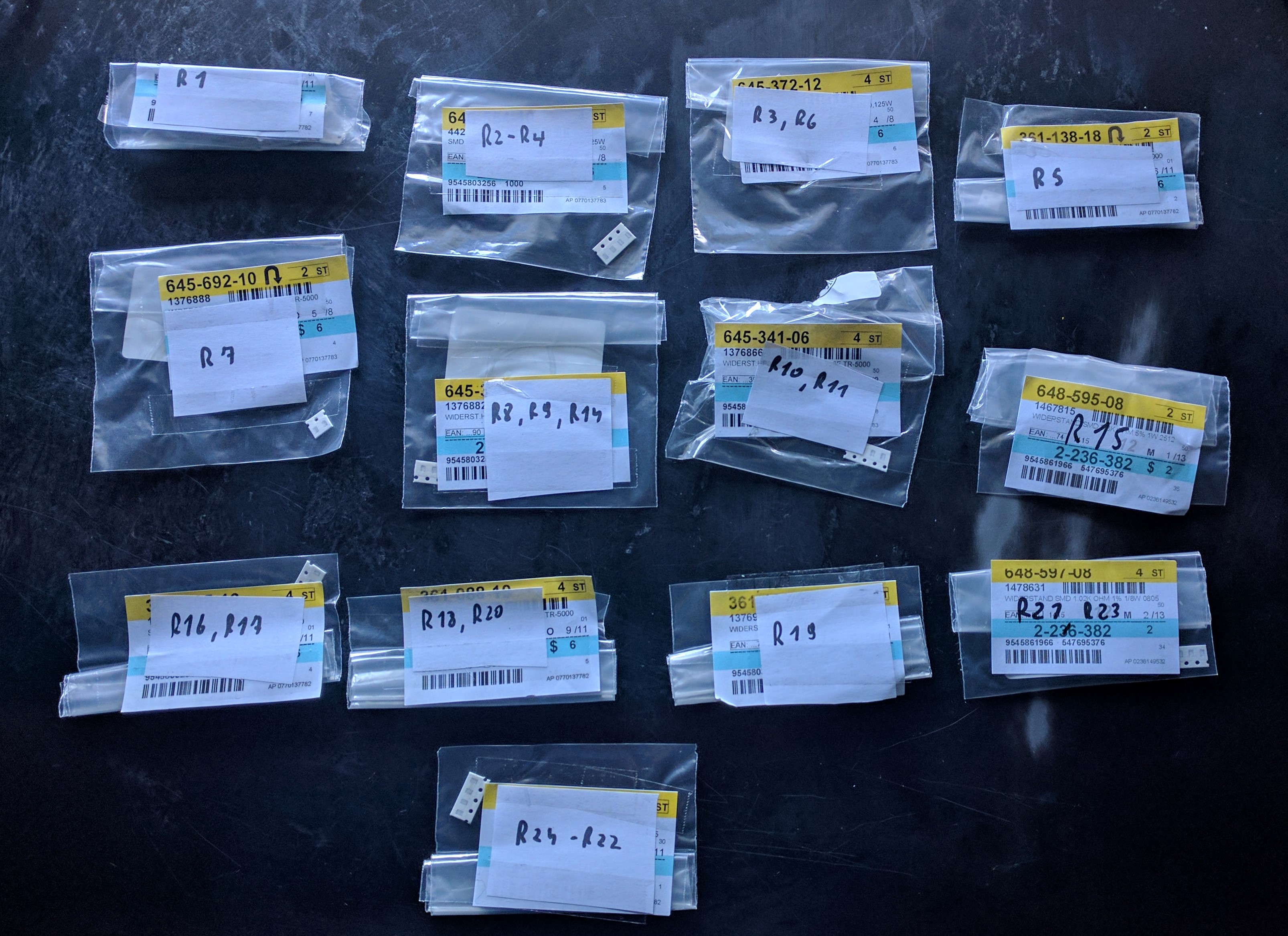
Refer to the Ultiboard design and the PCB silkscreen for the correct placement.
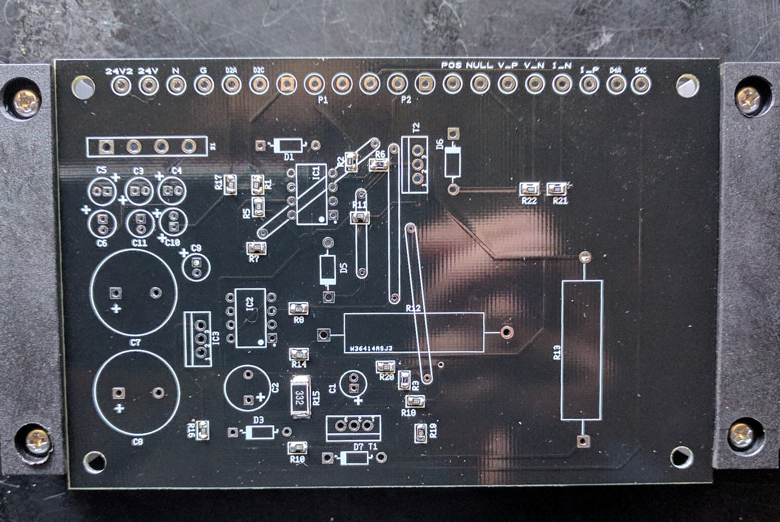
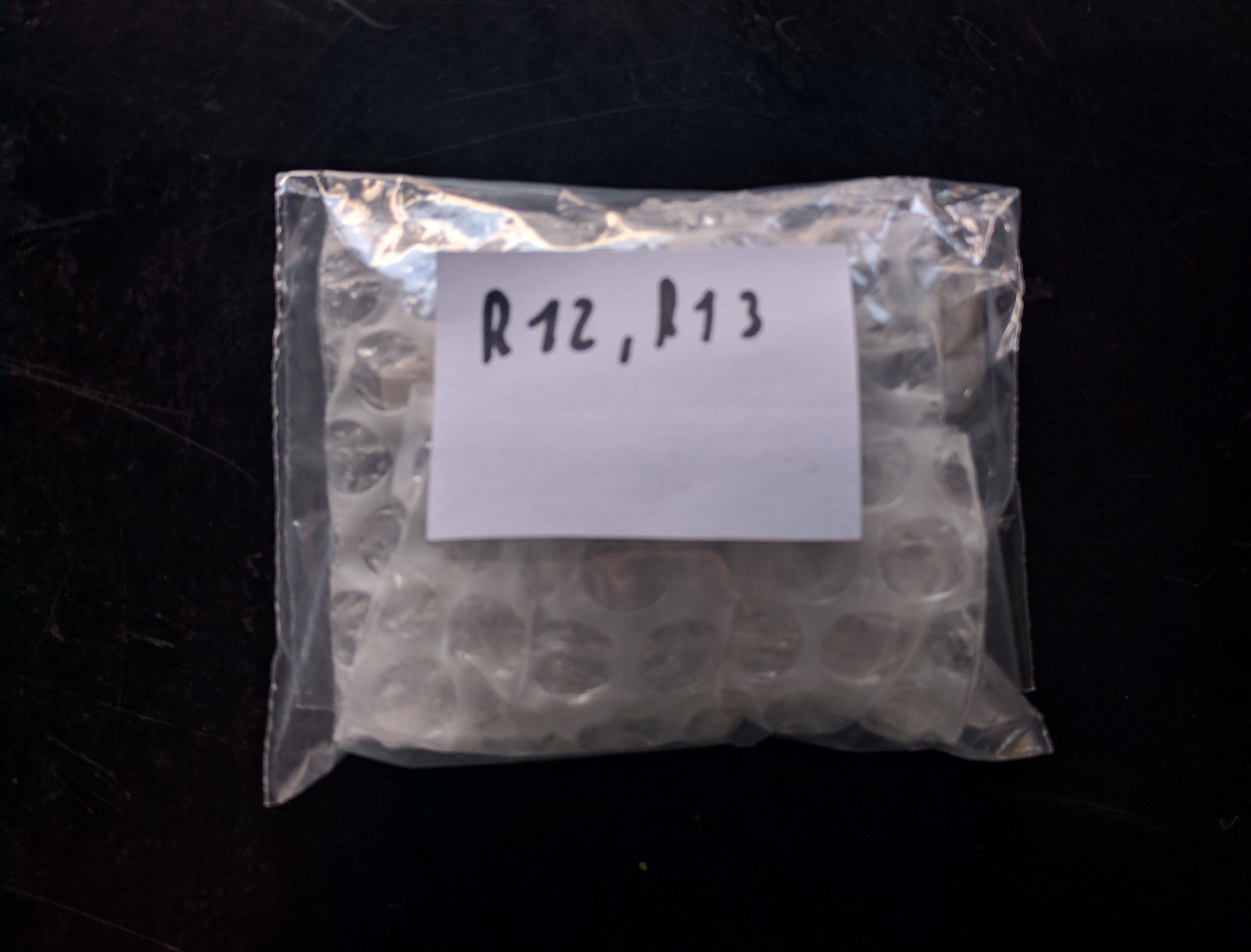
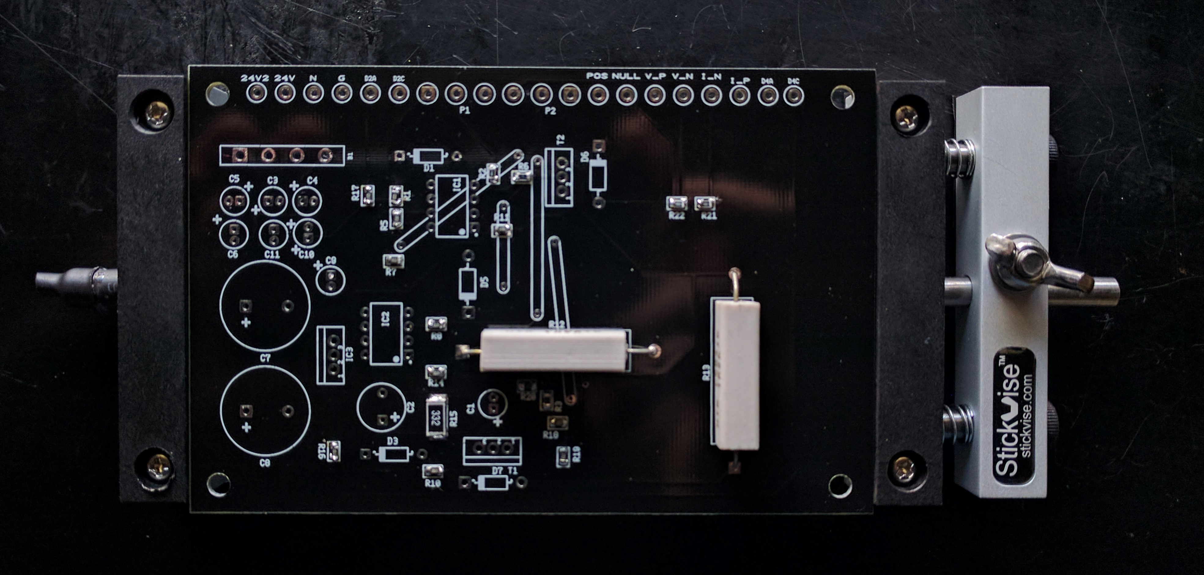
The only trough-hole resistors we have are R13 and R12.
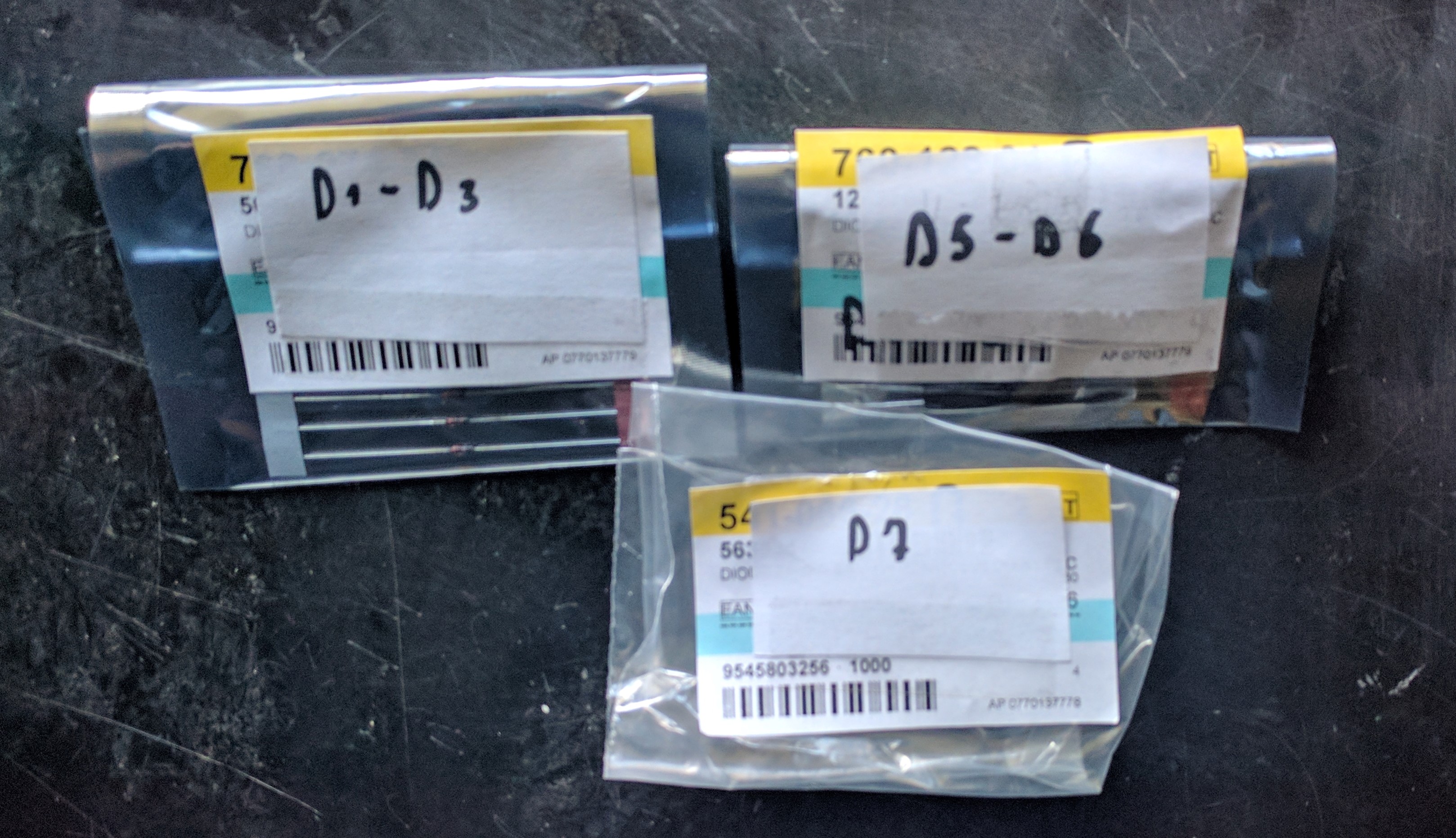
The next components will be the diodes.
Take D1, D3, D5, D6 and D7.
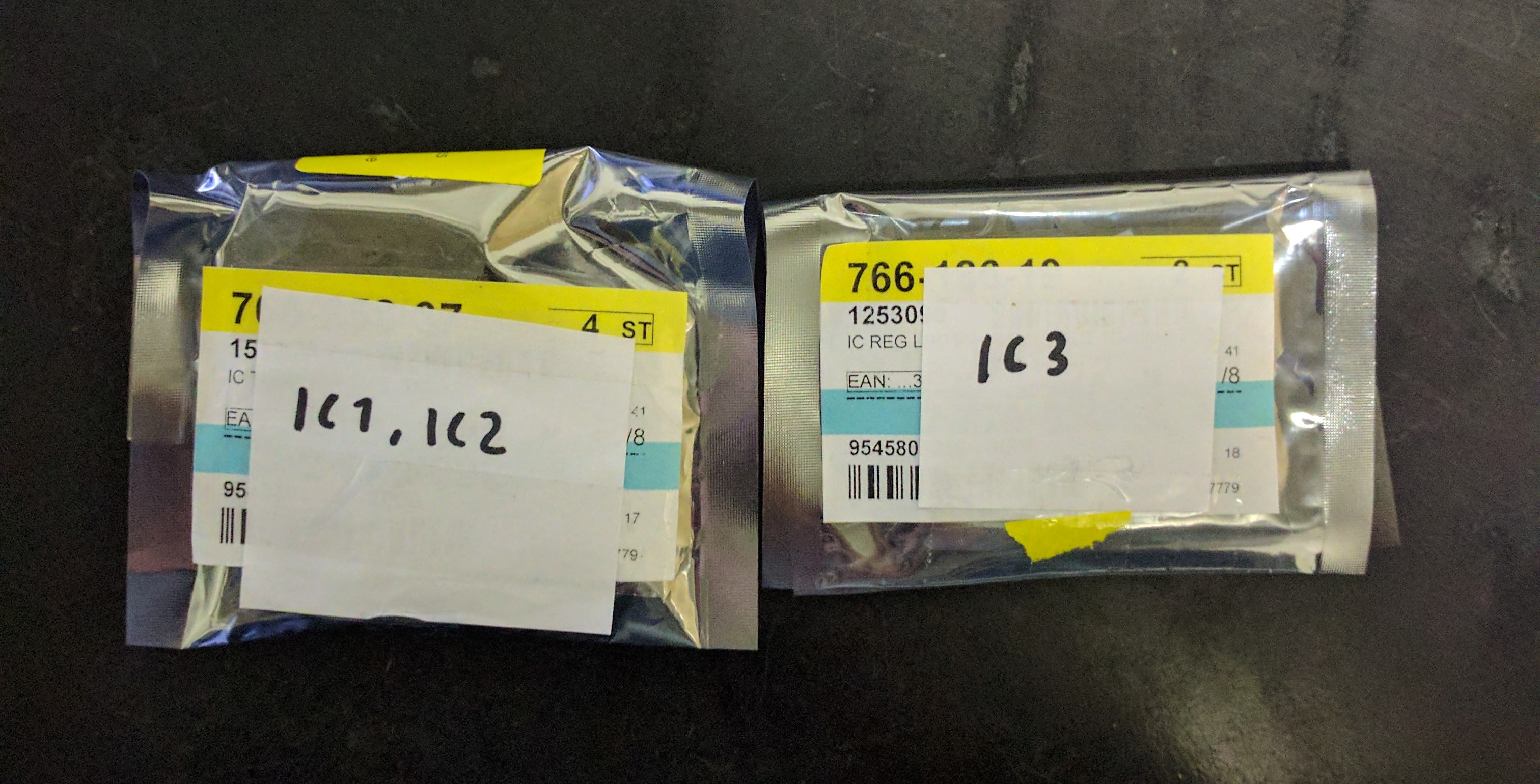
At this point, we decided to solder the IC’s; IC1, IC2 and IC3.
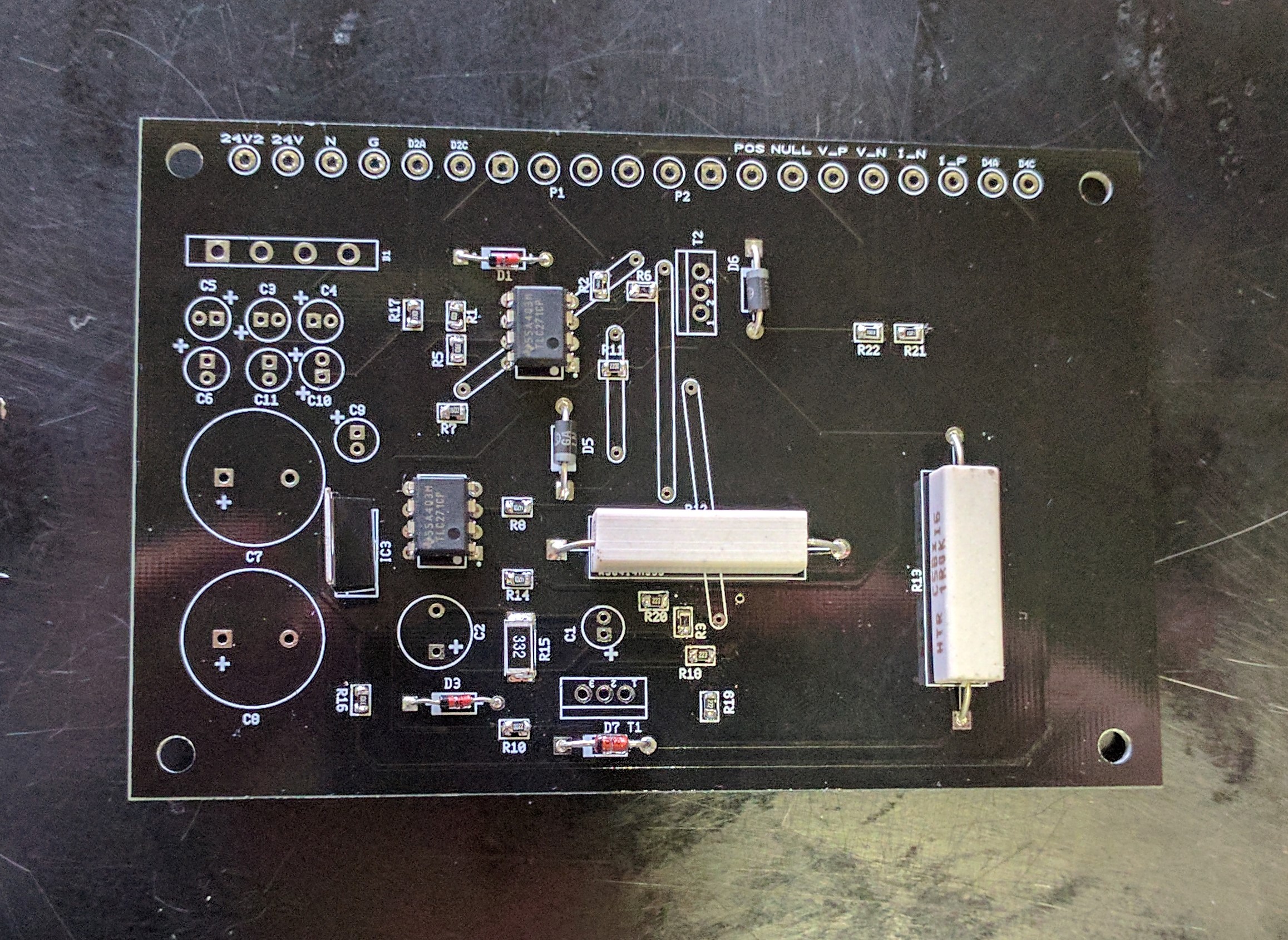
Now we will solder the MOSFET’s (T1 and T2).
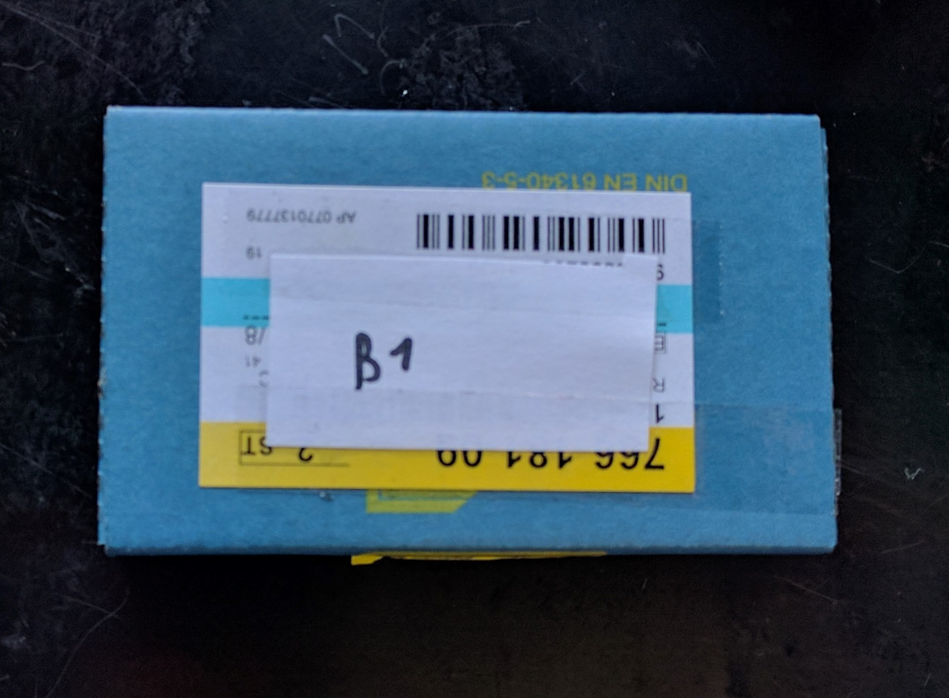
The next component is the bridge rectifier B1.
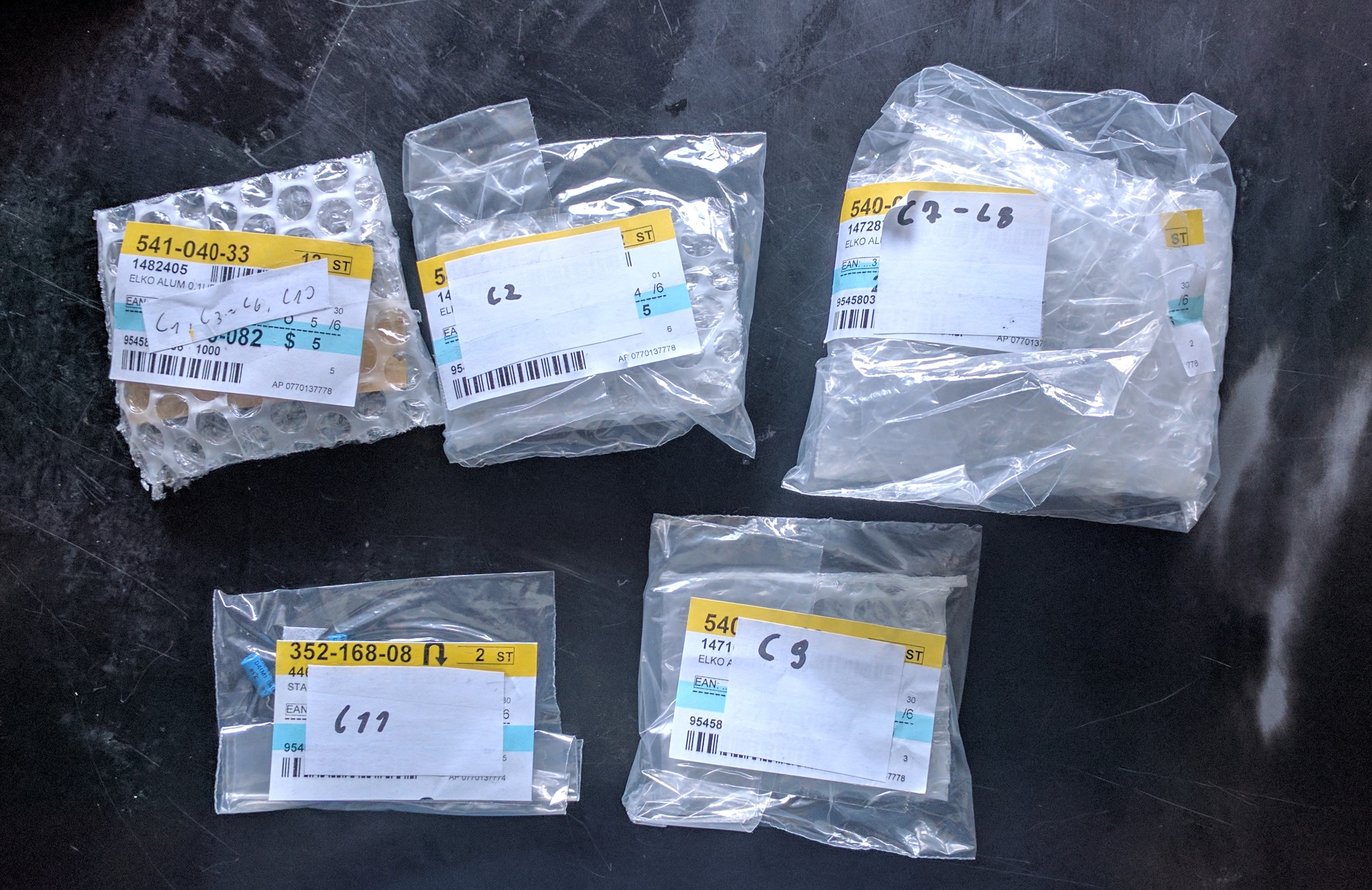
The following components will be the capacitors : C1, C2, C3, C4, C5, C6, C7, C8, C9, C10 and C11.
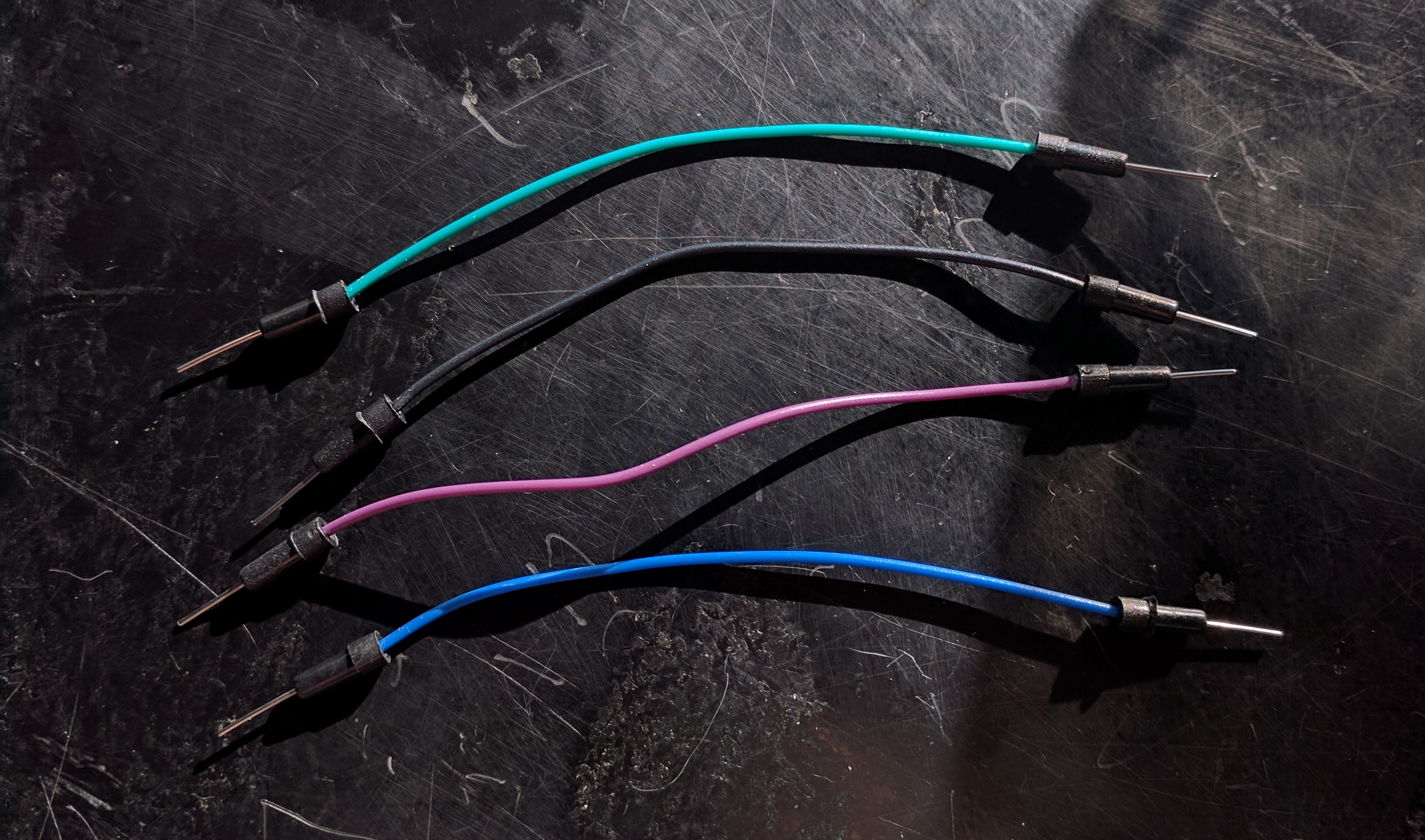
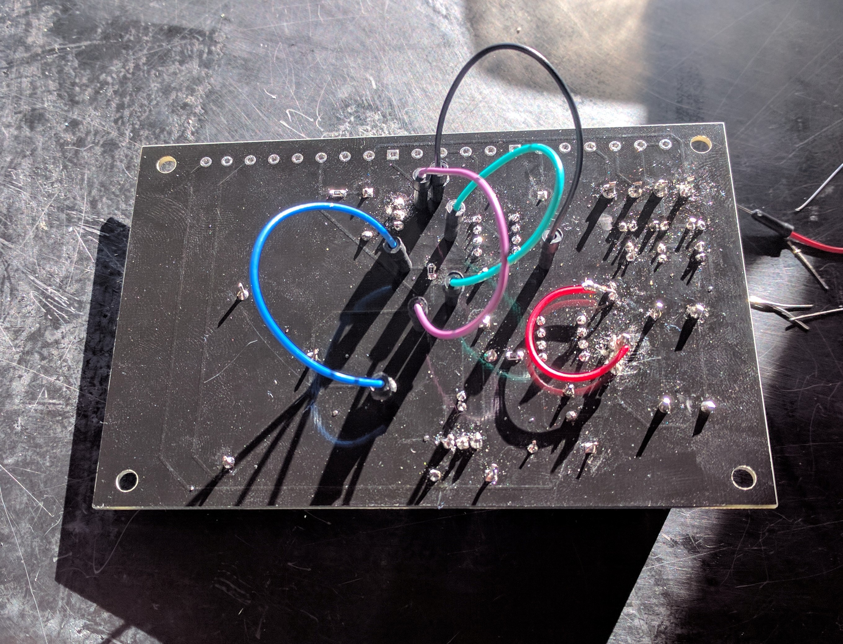
We have 4 jumper wires to solder.
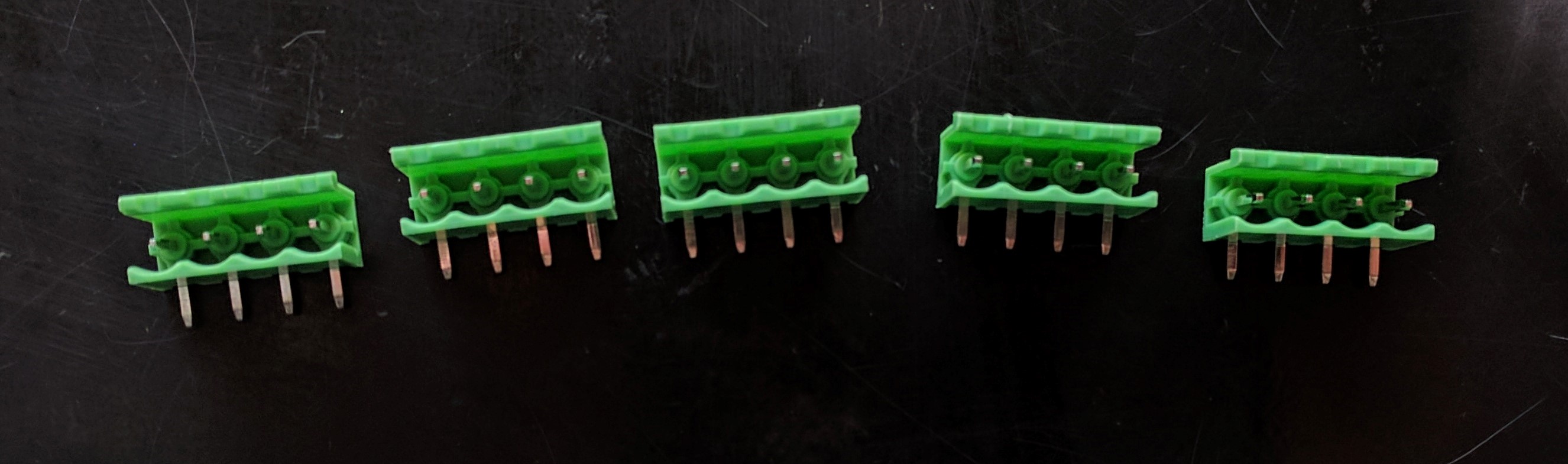
The last thing we will solder are the connectors, we need 5 pieces.
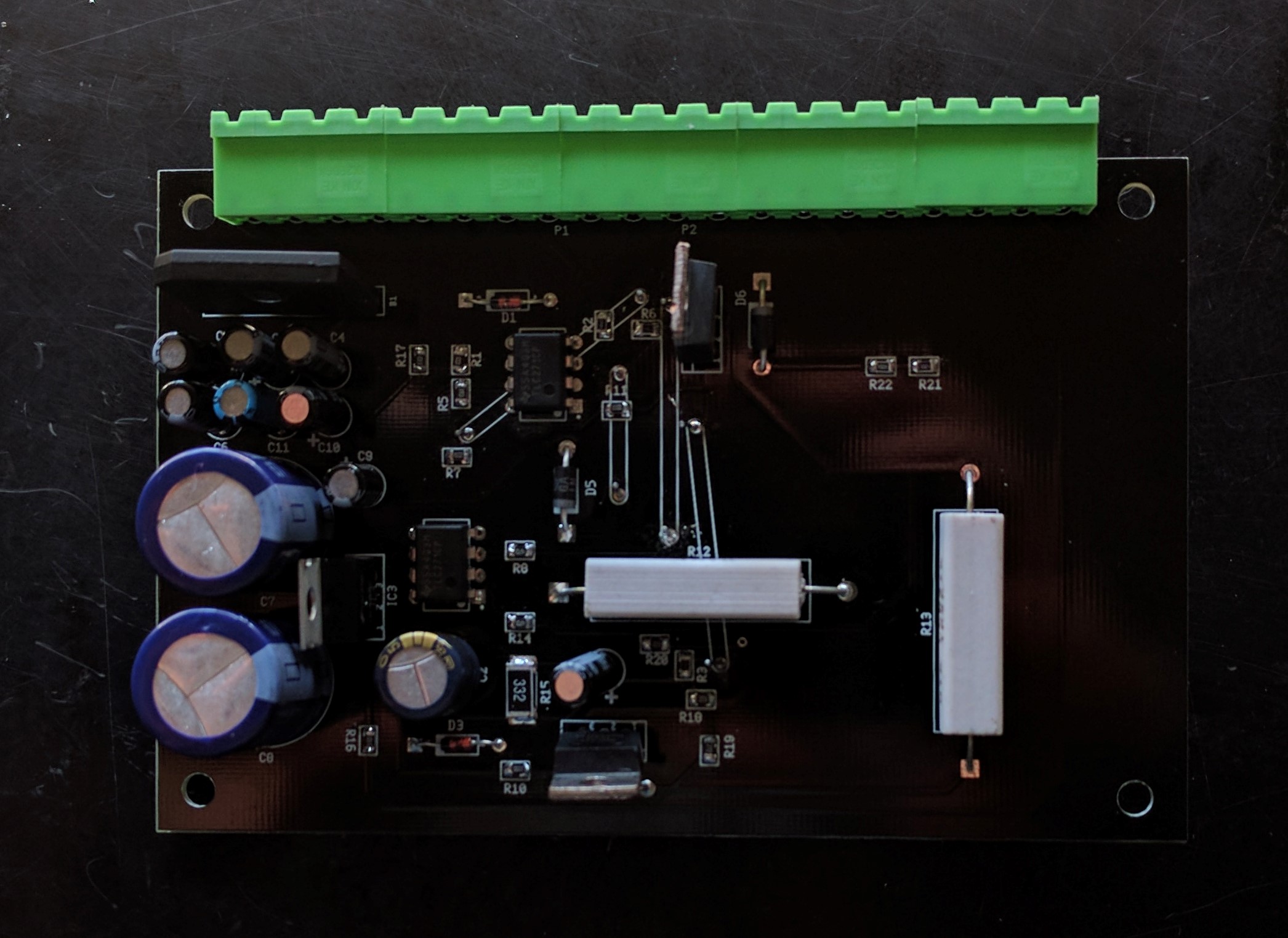
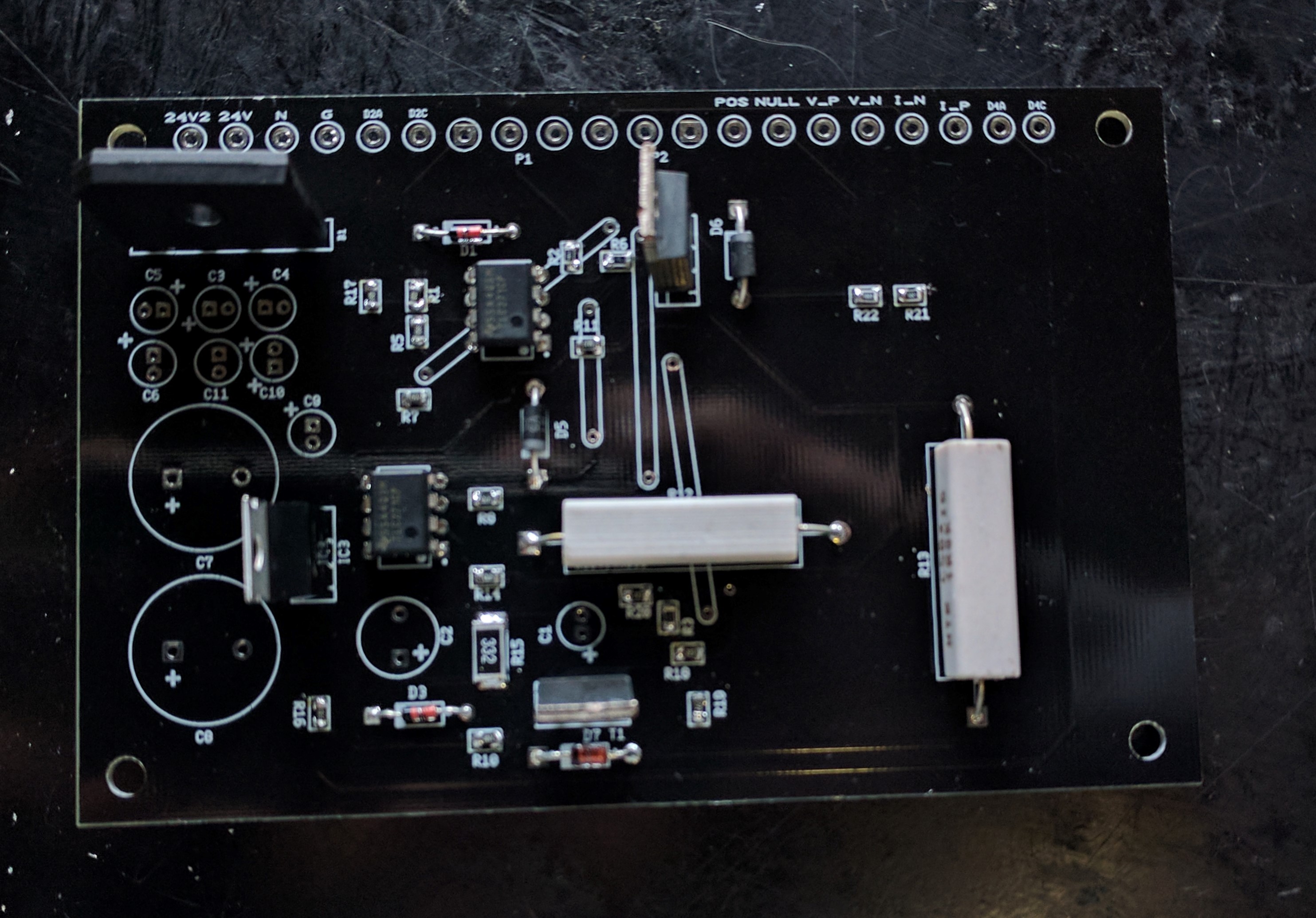
Now that the soldering is done, we can mount the PCB onto the case.
We start off by making the necessary marks.
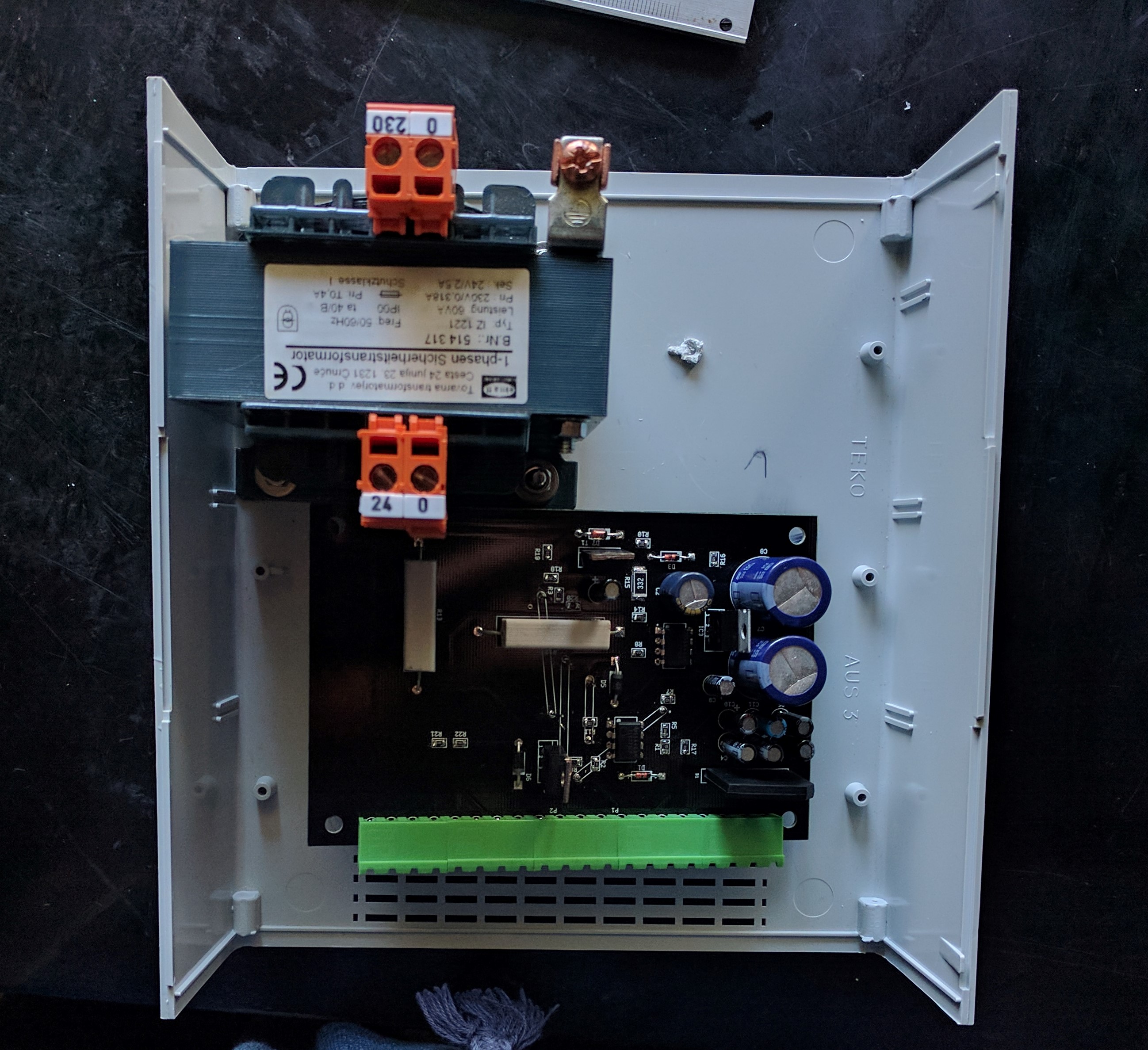
We drill the necessary holes and mount the PCB with nuts and bolts.
Test procedure
Front panel
Test if the 2 diodes (D2 and D4) work by connecting an external power supply and resistor.
Measure the ohmic regulation of the two potentiometers.
Check the measurements of the display and compare these to a multimeter.
Back panel
If the socket is plugged in and turned on, the measured voltage VAB should be 230V (ac).
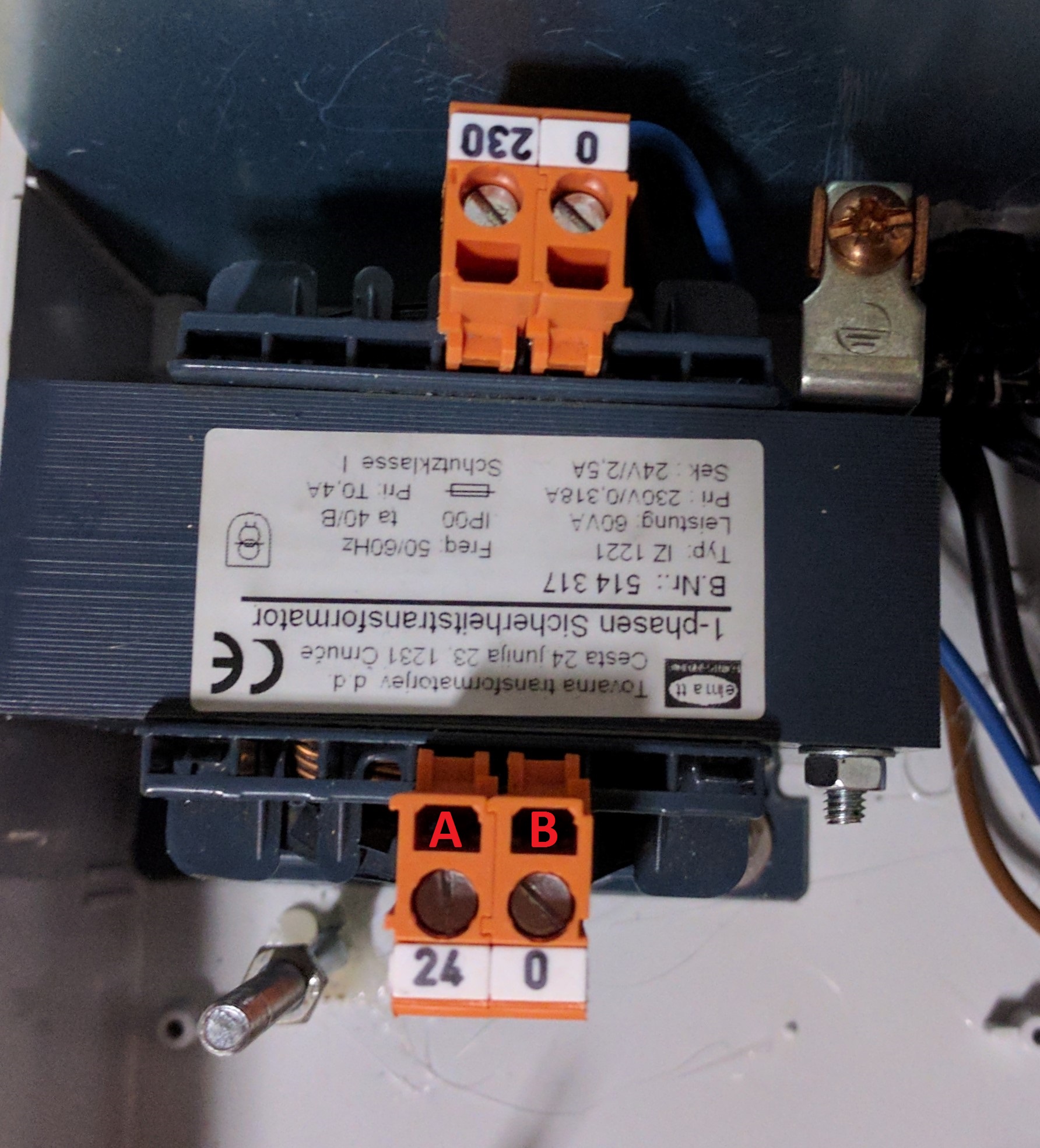
Transformer
With the socket connected to the primary winding of the transistor, the voltage VAB should be 24V (ac).
PCB
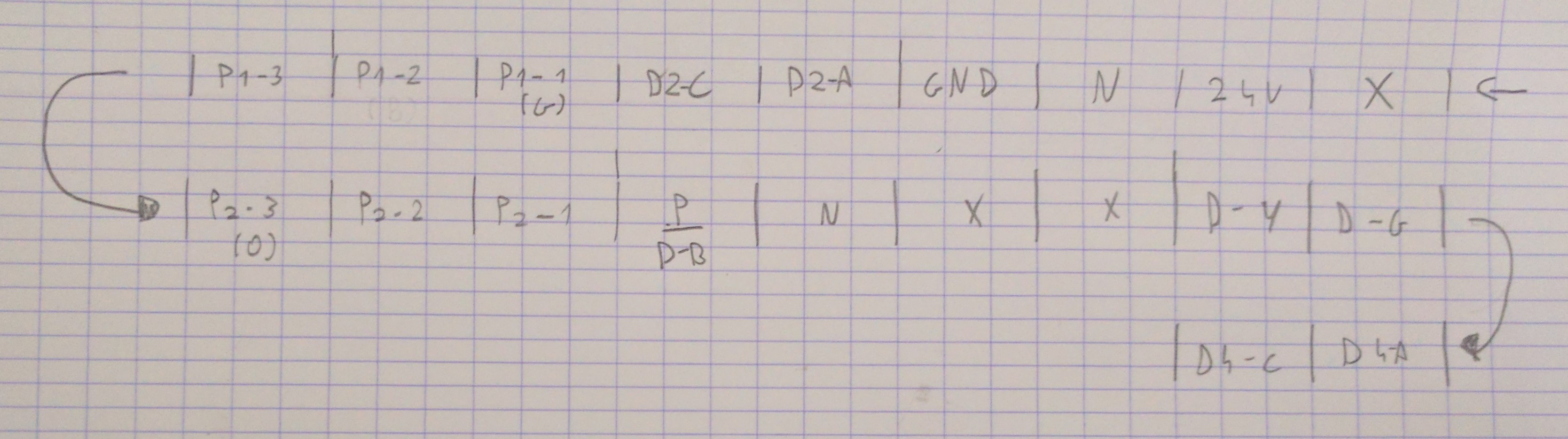
We will start with the wiring of the PCB, the pinout of the connectors is shown below.
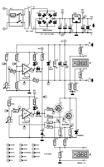
Next is the test-procedure of the PCB, we can do this on the basis of the scheme provided by “Elektuur”.