Encountered Difficulties
Problem 1
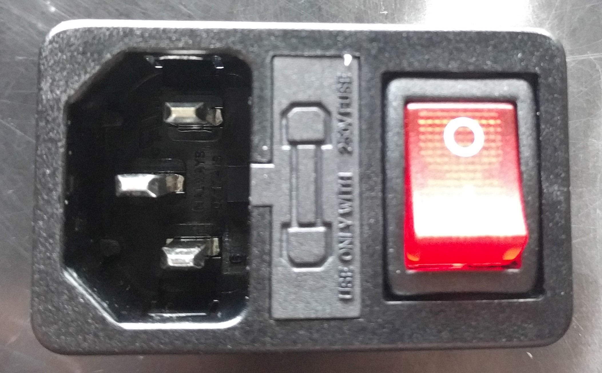
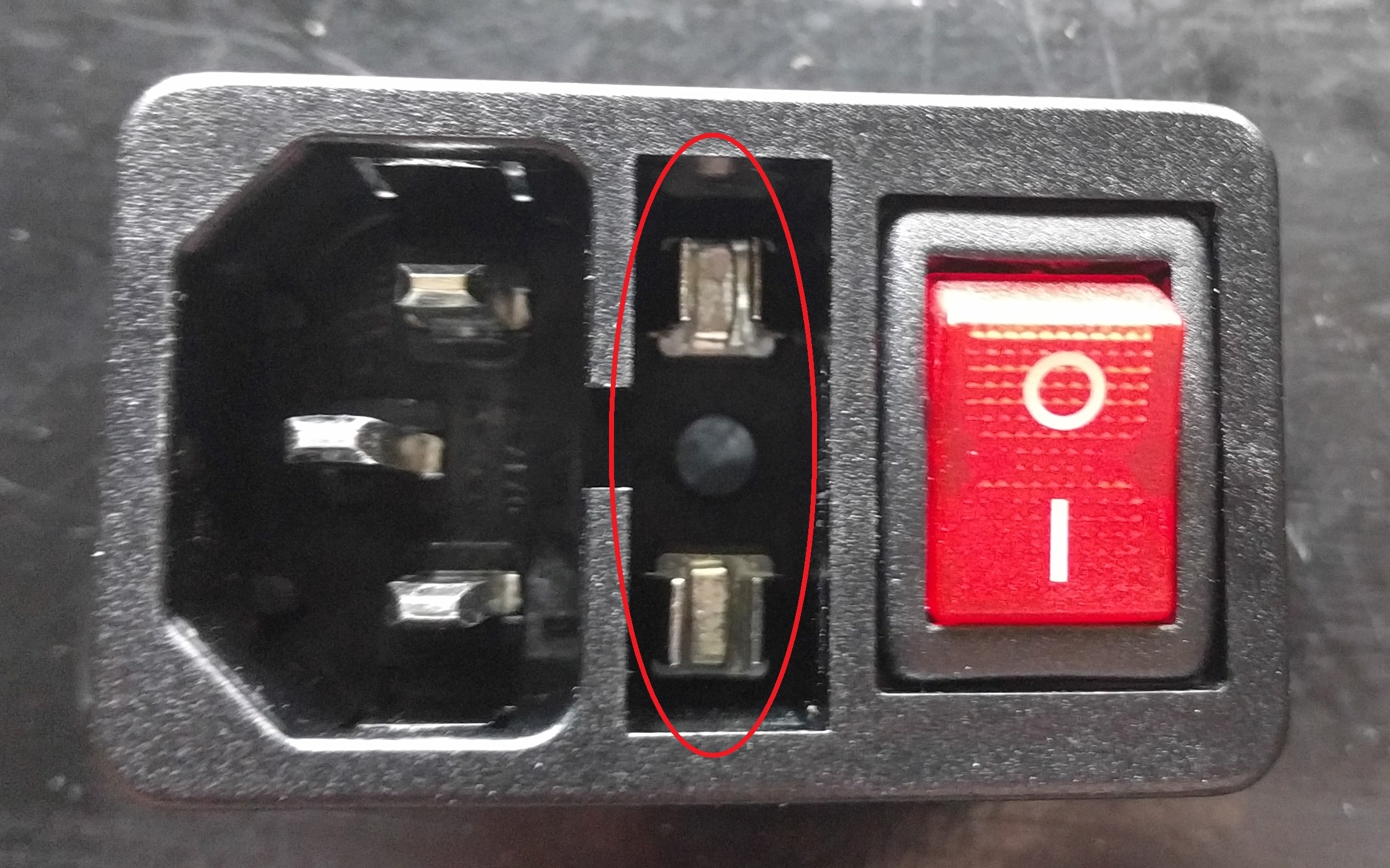
The first problem was that I didn’t realise that the built-in plug needed a fuse to operate. This was solved by just buying one from Ebay.
Problem 2
The second problem that I encountered affected the design process of the PCB quite a bit.
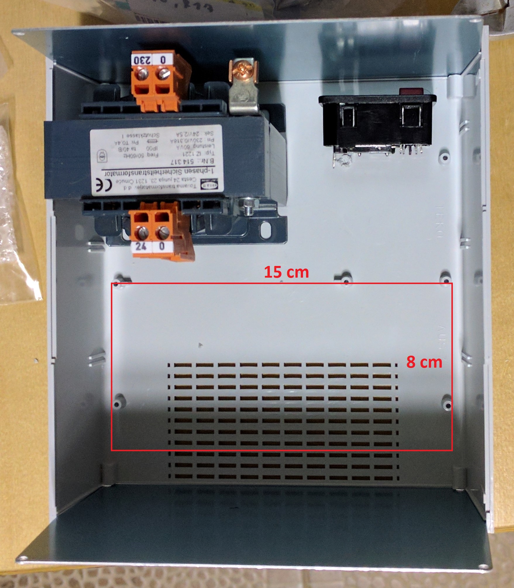
The issue was that I underestimated the size of the 230V-24V transformer. The result of this is that I had considerably less space for my PCB than I originally expected.
That’s why I had to design the PCB in a way where all the components were right next to each other, which made it a little bit claustrophobic.
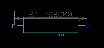
Problem 3
The third problem was that the footprint of R13 was too small, this was fixed by adjusting the dimensions in Ultiboard.
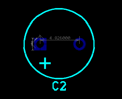
Problem 4
The fourth issue was that in Ultiboard, the space between the pins for C2 were too small. This was also rectified by adjusting them in Ultiboard.
Problem 5
The fifth was a potential problem.
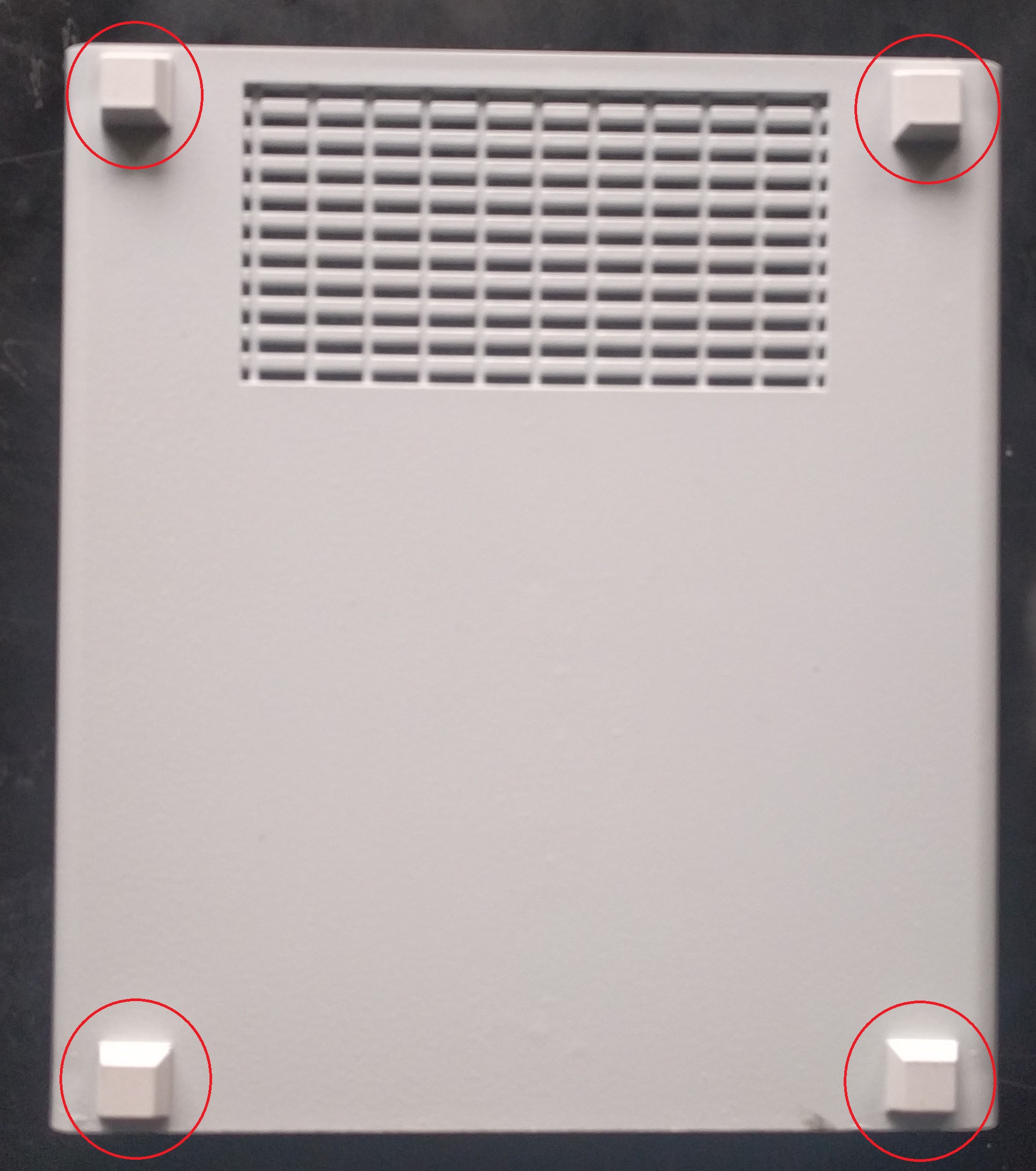
After considering how I would mount the transformer and the PCB onto the case, I decided to use regular nuts and bolts.
Then I realised that the bolts would cause an indentation underneath the case.
That’s when I decided to buy a pack of rubber feet from the local store and mount them onto the case.
µ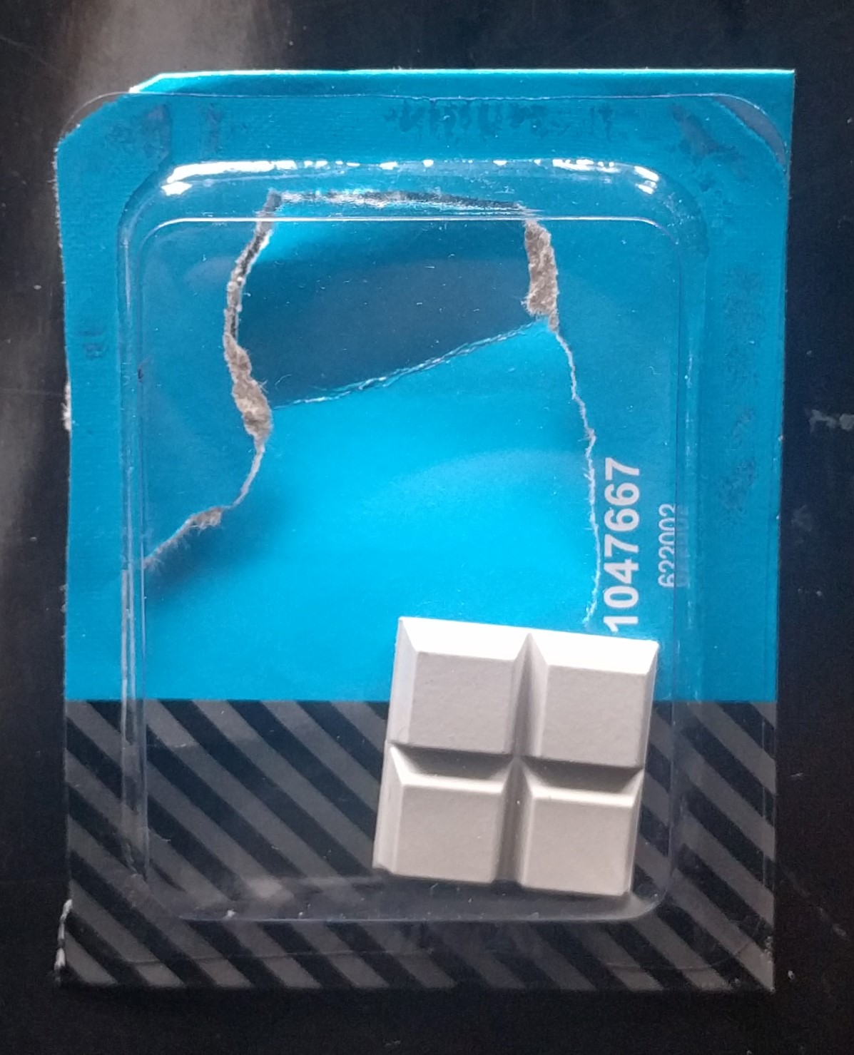
Problem 6
The next issue that I encountered was that the amount of pins on the connectors would not match the ones on the PCB;
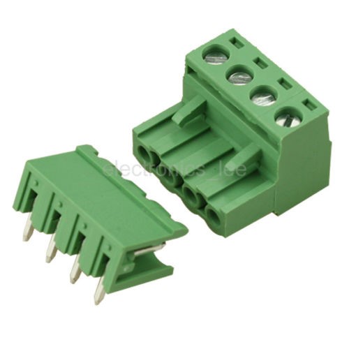

Pins on connector : 5*4 = 20
Pins on PCB : 19
If the PCB was ordered this way, I would have either had to shorten a connector to three pins or drill a hole in the PCB myself.
To avoid such mess I decided to make an extra no-purpose pin.
Problem 7
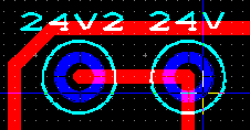
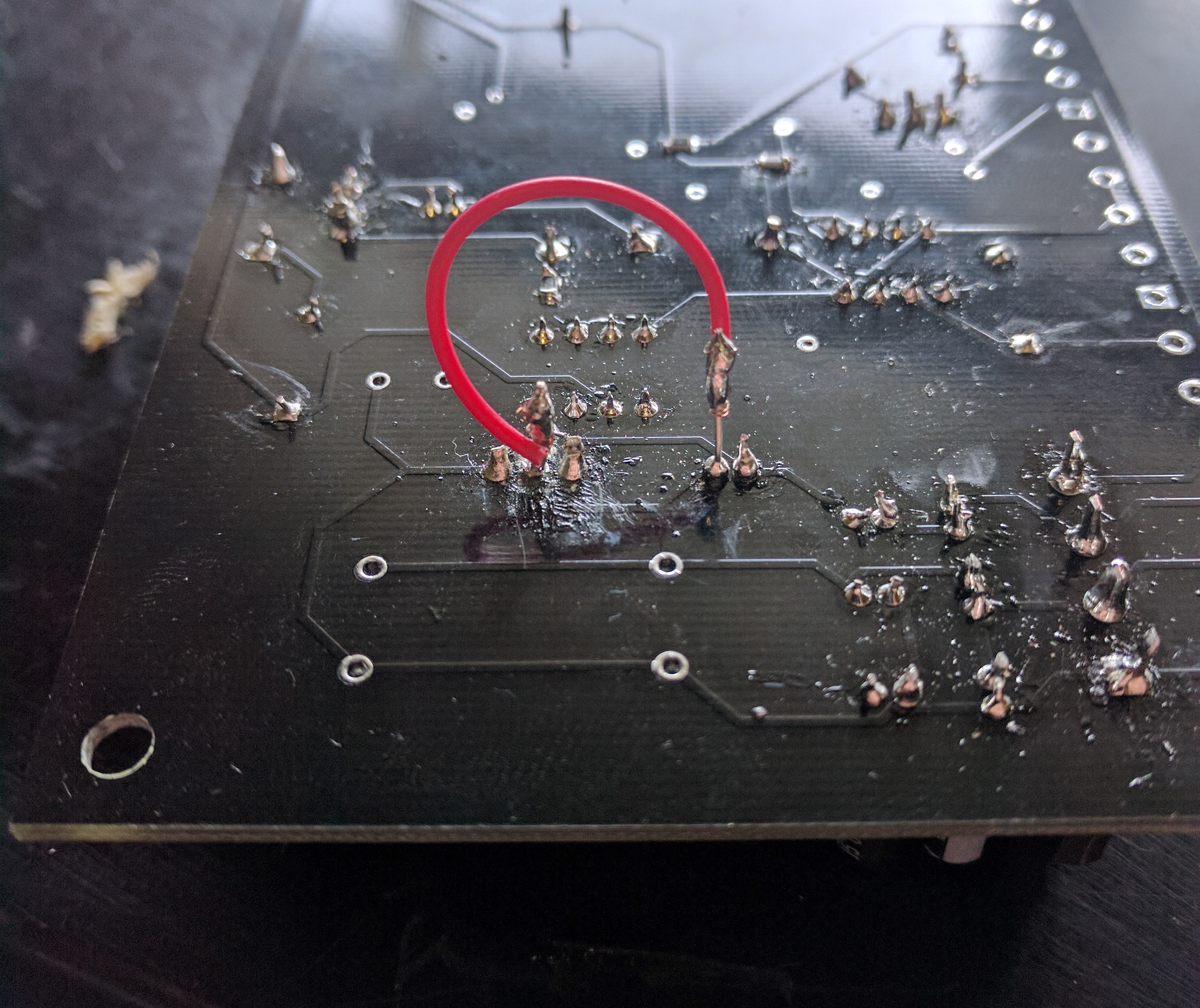
The following issue was that the pad of pin 2 of IC3 came off.
I had to take a jumper wire and make a manual connection from pin 2 of IC3 to the negative pin of C9.
Problem 8
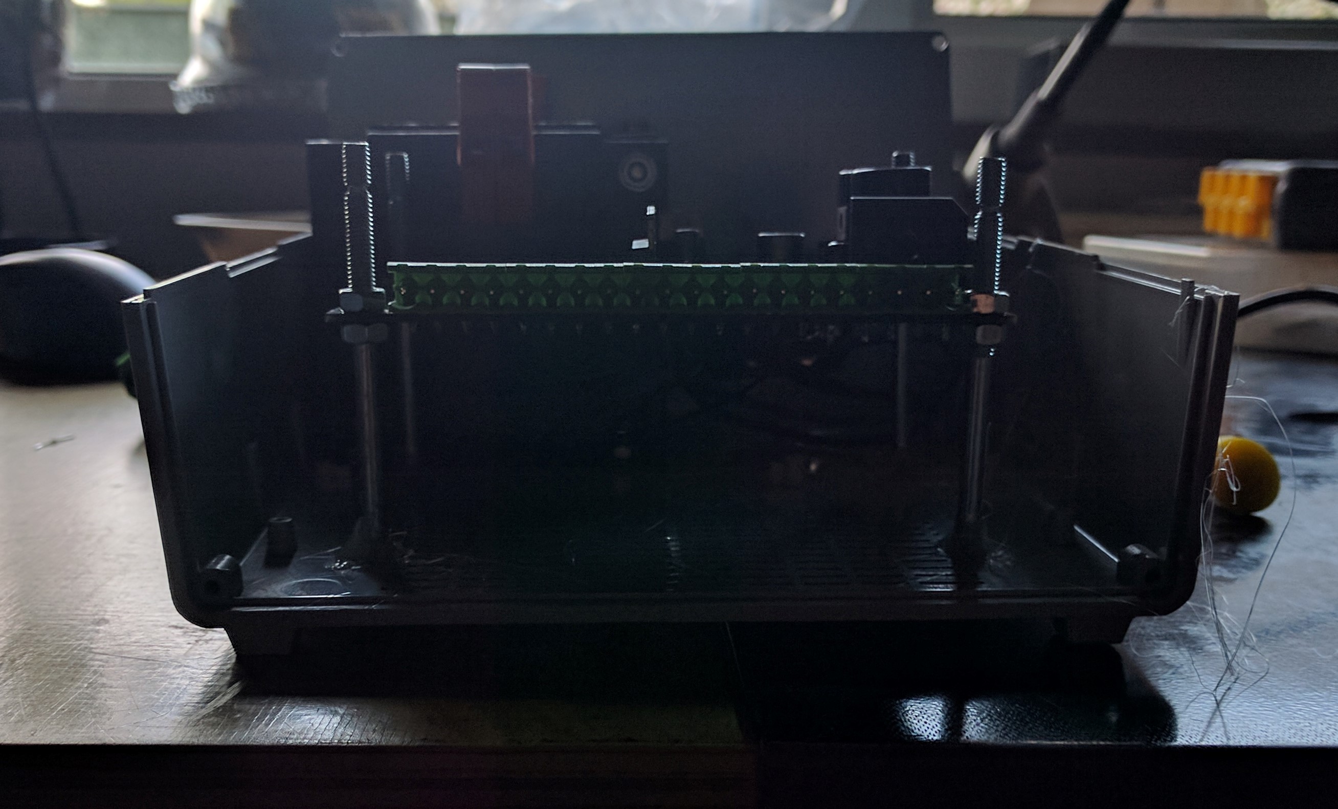
In when wiring the connectors, I noticed that the connectors blocked the area around the potentiometers on the front panel. This would prevent the front panel from being closed.
I had to use longer bolts to raise the PCB to avoid this.
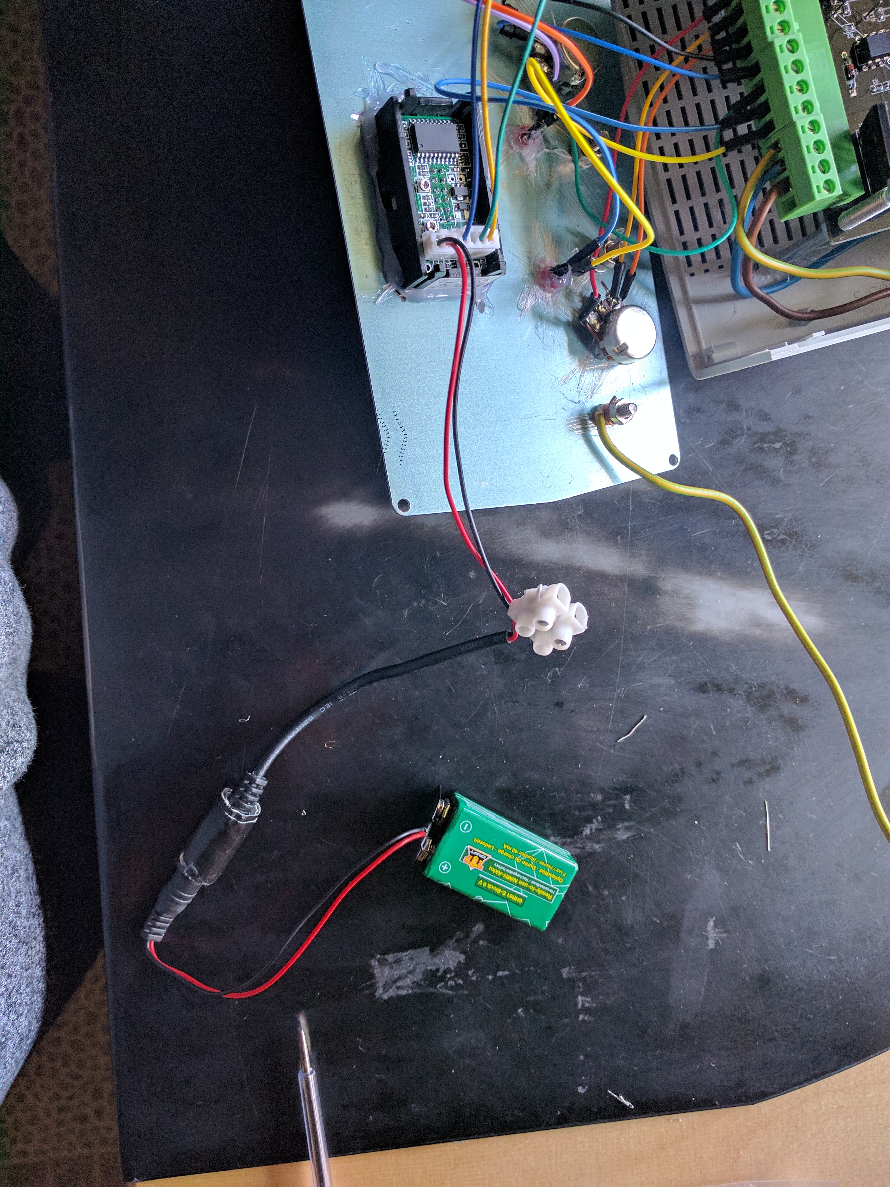
Problem 9
I didn’t realise that the display on the front panel needed an external power supply for it to function. This was solved by using a 9V battery as a power source for the display.